2 System Overview
Operator’s Manual 2 - 9
2.8 Dual-Probe Extend Module Overview
2.8.1 Parts and Names
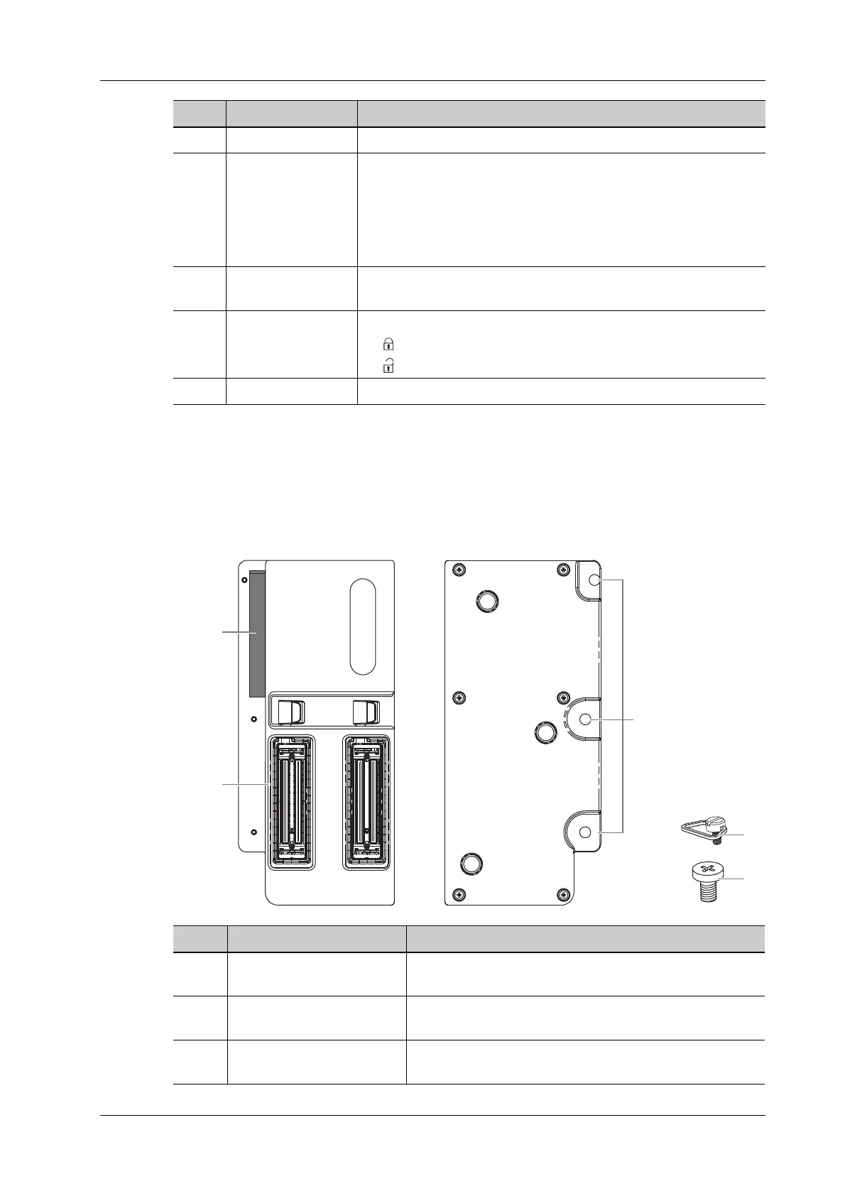
Figure 2-2 Dual-Probe Extend Module
9. Handle Used for carrying the system.
10. Control Panel Operator-system interface or control.
NOTE:
The buttons and knobs on the control panel may be different for
different product models. Please refer to the control panel of the
product for the actual buttons and knobs.
11. Probe port Connects a probe to the main unit; or connects a probe extend
module.
12. Probe locking lever Locks or unlocks the probe connected with the main unit:
• : locked symbol.
• : unlocked symbol.
13. Power input port Connects the power adapter.
No. Name Description
No. Name Description
1. Connector Connects to the probe port of the main unit, and extends
the probe port to two.
2. Probe port To extend ports for connecting probes, the middle one is a
docking port.
3. Fixing screw holes (×3) To fix the module to the main unit using the supplied
screws.
 Loading...


