α
Simple Application Controllers
What You Should Know Before Starting to Program 4
4-2
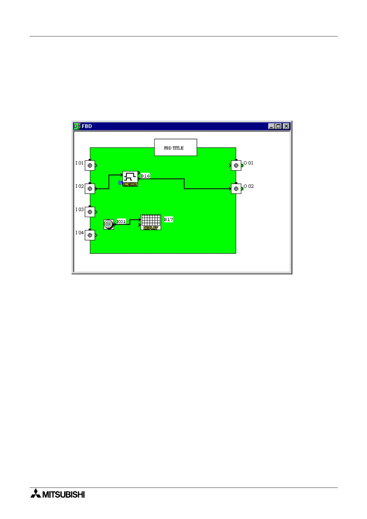
4.2 The Function Block Diagram base
The Function Block Dia
ram
FBD
base provides the platform upon which the pro
ram for the
α
controller is constructed. The FBD base consists of a lar
e wirin
area
reen b
default
, a
title box and input and output rectan
les verticall
alon
the ri
ht and left hand sides, respec-
tivel
. Pro
rammin
components are placed on the wirin
area or in the rectan
les, and con-
nected b
wires to construct the controller pro
ram. The FBD base is also known as FBD
Wirin
area.
The user can perform the followin
ten operations usin
FBD base screen. Refer to Chapter
Six for more details.
1. Place the I/O si
nals and functions usin
the Accessories Toolbar.
2. Assi
n parameters to functions.
3. Wire the various pro
ram components to
ether
with the help of Wirin
Anal
ser
.
4. Load the Pro
ram lo
ic and I/O device’s information to the
α
Controller.
5. Invoke Auto FBD Wizard to be
in to pro
ram with directions.
6. Test the pro
ram lo
ic with Internal Devices
Input and Output si
nals placed in the
FBD wirin
area
.
7. Simulate and check the pro
rammin
lo
ic without connectin
an
α
Controller. The
user can:
- force input si
nals ON/OFF
- chan
e function parameters
timers, counters, analo
data, etc.
- displa
comments or function values on screen
- Monitor component status via wire colors
ex. Red Wire = OFF, Blue Wire = ON
8. Read information from an
α
Controller and recreate the Pro
ram on the FBD base.
9. Monitor an
α
Controller that is in operation.
10. Print the FBD screen and component information shown on screen.

 Loading...