α
Simple Application Controllers
Function Block Diagram (FBD) Operation 6
6-3
6.2.3 System Memory Bits
These five S
stem Memor
bits act as di
ital inputs and can be placed on the
FBD base onl
. The memor
bits have the followin
set functions.
M01: Alwa
s ON
M02: Alwa
s OFF
M03: C
cles between 0.5 seconds On and 0.5 seconds Off
M04: Turns On when there is a Real Time Clock Error
M05: Turns On when the SummerTime clock is On.
M06: AS-Interface Communication Error
M07: AS-Interface Power Suppl
Error
These ke
s can also be found under the IN headin
of the Accessories Toolbar. The names of
the si
nals will appear when the mouse arrow is placed on the icon.
6.2.4 Function Blocks
There are twent
-two function blocks that can be used with the
α
controller. The
fall into two
cate
ories - Lo
ic and Standard. The function blocks can be placed on the FBD base onl
.
6.2.5 The Logic Blocks
The six Lo
ic Blocks - AND, OR, NOT, XOR, NAND, NOR - can receive onl
di
ital inputs. These blocks turn their Output on dependin
on the ON/OFF
conditions of their Inputs. Please see the Help File for a detailed description of
each block.
The Lo
ic Blocks can be found under the LOGI headin
in the Accessories
Toolbar. The names of the blocks will appear when the mouse arrow is placed
on the icon.
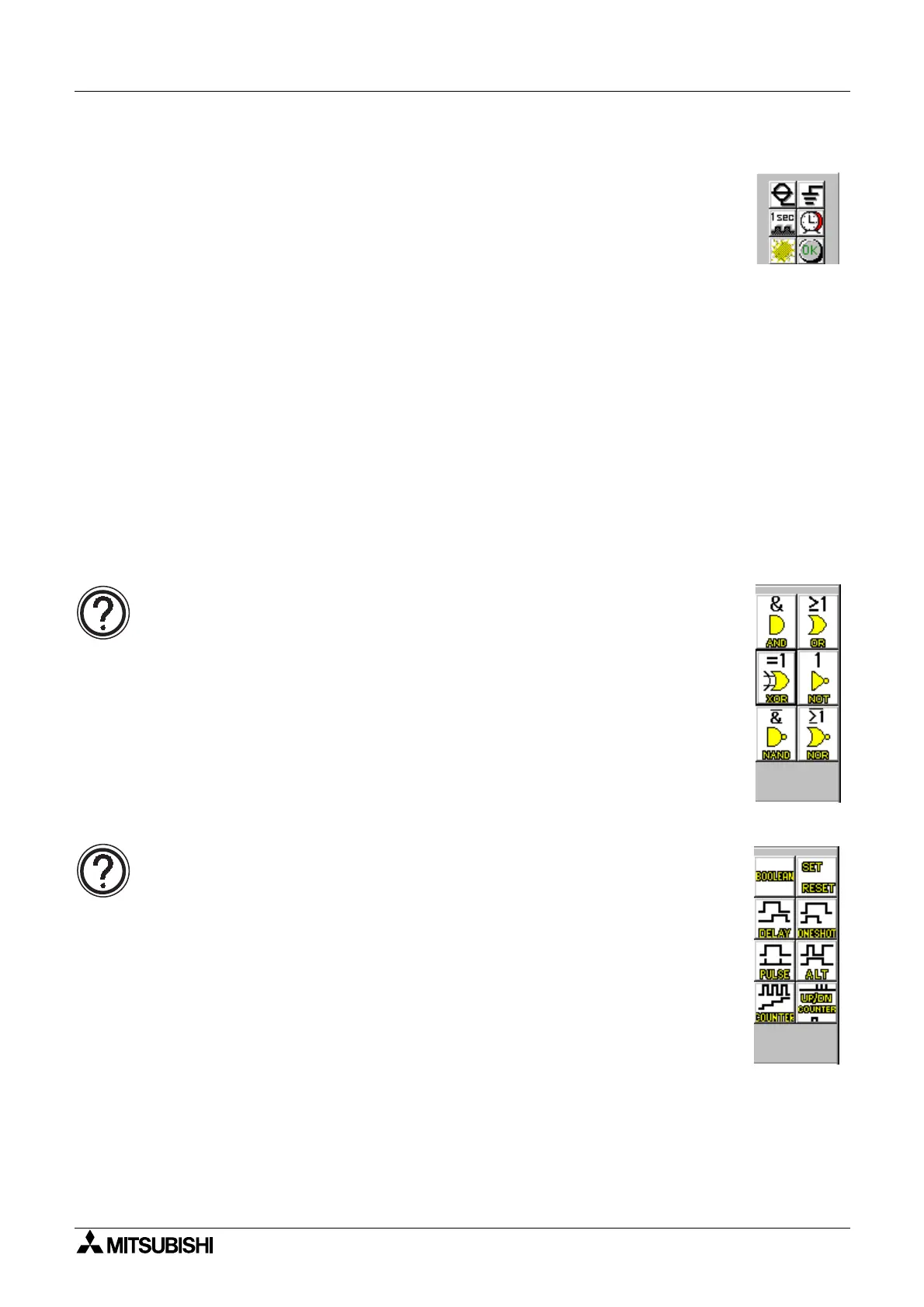
6.2.6 The Standard Function Blocks
The sixteen Standard Function Blocks include the BOOLEAN, SET/RESET,
DELAY, ONE SHOT, PULSE, FLICKER, ALTERNATE, COUNTER, UP/DOWN
COUNTER, COMPARE, TIME SWITCH, OFFSET GAIN, DISPLAY, ZONE
COMPARE, SCHMITT TRIGGER, and the HOUR METER. Please see the
Help file for a detailed description of each block.
The Standard Function Blocks can be found under the FUNC headin
of the
Accessories Toolbar. The names of the blocks will appear when the mouse
arrow is placed on the icon.

 Loading...