α
Simple Application Controllers
What You Should Know Before Starting to Program 4
4-9
4.9 AS-Interface Programming
AS-Interface modules are available for the 20 I/O controller and can be pro
rammed with the
VLS software. The followin
special s
mbols appl
onl
to the AS-Interface network
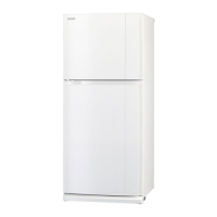
4.9.1 ASI Input Icon
There is an AS-Interface icon available in the “In” Menu. A total of four ASI “Link
In” inputs can be added to the FBD base. When the “Link In” is added to the
FBD base, a dialo
box pops up that allows the link to be numbered from E01
to E04. Error messa
es are
iven if the wron
controller t
pe if an ASI link
number is used twice. The AS-Interface inputs do not count towards the
number of
α
Inputs available.
4.9.2 ASI Output Icons
There is an AS-Interface icon available in the “Out” Menu. A total of four ASI
“Link Out” outputs can be added to the FBD base. When the “Link Out” is
added to the FBD base, a dialo
box pops up that allows the link to be num-
bered from A01 to A04. Error messa
es are
iven if the wron
controller t
pe if
an ASI link number is used twice. The AS-Interface Outputs do not count
towards the number of
α
Outputs available.
4.9.3 Active/Passive State
The
α
can be switched from an Active to a Passive state on the AS-Inter-
face network b
chan
in
the state on the N01 Control Icon. In the Active
State, N01=0, communication is possible over the network. This icon can
be found in the “Out” Menu next to the ASI “Link Out” icon.
When multiple
α
units are added to a network, each slave must be
iven
an address. In order to address the slaves from the Master station, onl
one unaddressed
slave can be active at an
one time. Once a slave has an address, another passive slave can
be turned to an active state to receive its address. Please refer to the AL-ASl-BD manual and
the manual for the ASI Network Master controller.
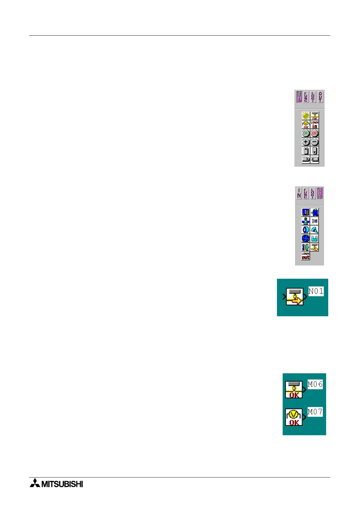
4.9.4 ASI System Bits
There are two s
stem bits dedicated strictl
to the ASI network:
M06: AS-Interface Communication Error
M07: AS-Interface Power Suppl
Error
Note: The ASI Network line is connected to the AL-ASI-BD for both Power
and communication purposes.

 Loading...