α
Simple Application Controllers
Function Block Diagram (FBD) Operation 6
6-2
6.2 The Program Edit Mode - Begin to Program
Pro
rams for the
α
controller can be created and edited from the Pro
ram Edit Mode. Pro
ram
Edit is the default mode for the VLS software. The
α
is pro
rammed b
placin
items on the
FBD Base and connectin
the various components to
ether with the wirin
anal
zer. There
are five t
pes of s
stem components that can be placed on the FBD base. A short description
of the function and placement locations possible for the various components follows.
6.2.1 Inputs
S
stem Inputs receive data from the devices wired to the actual controller and
can be either the di
ital or analo
si
nal t
pe. The di
ital units transmit an On
or Off si
nal; Analo
inputs transfer a data value. The icons can be found under
the IN headin
of the Accessories Toolbar at the left of the FBD base.
The di
ital si
nals can be placed on the Input rectan
les at the left of the FBD
base or on the base itself. Each icon functions in the same wa
. The different
icons have been developed to aid in the documentation and understandin
of
the pro
ram. Use an input icon that corresponds to the actual input device to
be connected to the controller. The names of the si
nals will appear when the
mouse arrow is placed on the icon.
The analo
si
nals can be placed onl
in Input Rectan
les I01 - I08. The
controller inputs act as an 8 bit Analo
/Di
ital converter when the analo
si
nal
is placed in the Input Rectan
les.
Four AS-Interface bits, E01 - E04, are available when usin
the 20 I/O versions
of the Alpha controller and VLS Version 1.30 or above. These inputs can be
placed an
where on the FBD base and will not be counted toward the number
of s
stem Inputs.
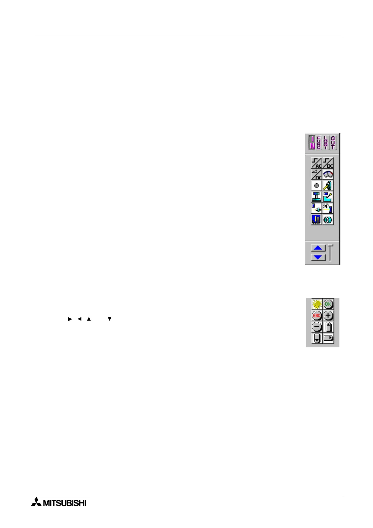
6.2.2 Front Panel Keys
There are ei
ht si
nals that correspond to the front panel ke
s and these
si
nals ma
be used as additional di
ital inputs. These are the ESC, OK, “+”,
“-”, , , and ke
s. Press the front panel ke
s while the
α
controller is in
Run mode to active the si
nals.
These ke
s ma
be placed onl
on the FBD Base and can be found in the IN
headin
of the Accessories Toolbar. The names of the si
nals will appear
when the mouse arrow is placed on the icon.

 Loading...