α
Simple Application Controllers
Function Block Diagram (FBD) Operation 6
6-10
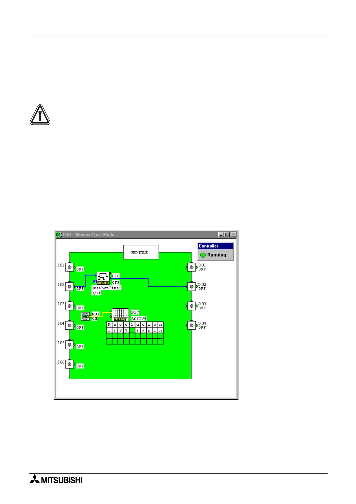
6.7 The Monitor Mode
The Monitor Mode can be used to monitor the current conditions of an
α
controller that is
runnin
a pro
ram. The
α
controller must be connected to the PLC via the AL-232CAB cable
and runnin
or, when Monitor Mode is started an error dialo
box will appear.
The contents of the VLS memor
and the
α
controller memor
must be the same before
monitorin
can take place. The VLS packa
e will read the contents of the
α
controller
continuousl
and update the information accordin
l
. Chan
es made to pro
ram parameters
will be transferred to the controller and will affect the operation of the e
uipment.
6.7.1 Entering the Monitor Mode
Enter the Monitor Mode b
clickin
on the Monitor Icon or b
usin
the Monitor Start command
in the Controller Menu.
Like the Simulation Mode, the di
ital wire connections will chan
e color so that outputs pins
that are On will become red and output pins that are Off will become blue.
These colors can
be chan
ed in the Options menu when in the Pro
rammin
Mode
. The components will all be
labeled with their number
I01, B02, O02, K08, etc.
, On/Off status, timer values, counter
values, Priorit
Settin
s, and other parameter values.
The controller status
RUNNING or STOPPED
will be monitored continuousl
and will be
displa
ed.

 Loading...