α
2 Simple Application Controllers
Introduction 1
ENG-4
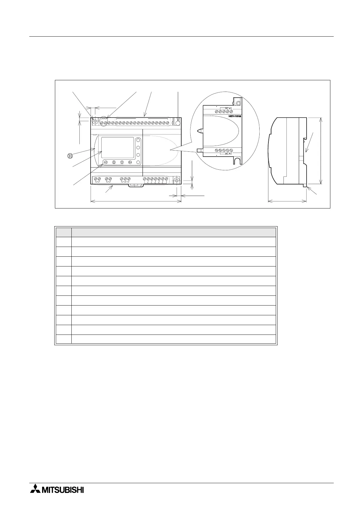
1.3 Dimensions and Each Part Name
Figure 1.1: Each Part Name
Table 1.4: Each Part Name
Ref. Item Description
1 Mounting hole, φ4.2 mm
2 Power terminals
3 Input terminals
4 Mounting screw for the extension cover or extension module
5 Extension cover or extension module
6 Groove for DIN rail mounting (Width of DIN rail 35mm <DIN EN 50022>)
7 DIN-RAIL mounting clips
8 Output terminals
9 Operation keys
10 Liquid crystal display
11 Programming port cover
OUT1
OK
-
+
ESC
OUT3
9
RELAY
OUTPUT
65
OUT
8
OUT2 OUT4
7
D C IN P U T
151413121110987654321(B )(A )
+-
24V D C
POW ER
AL2-24M R -D
124.6(4.91")
90(3.54")
6(0.24")
4(0.16")
4(0.16")
6(0.24")
52(2.05")
+-E01E02
+E03-E04
 Loading...


