Contrôleur
α
2
AL2-ASI-BD 9
FRE-45
FRE
9.3 Câblage et Installation
9.3.1 Installation
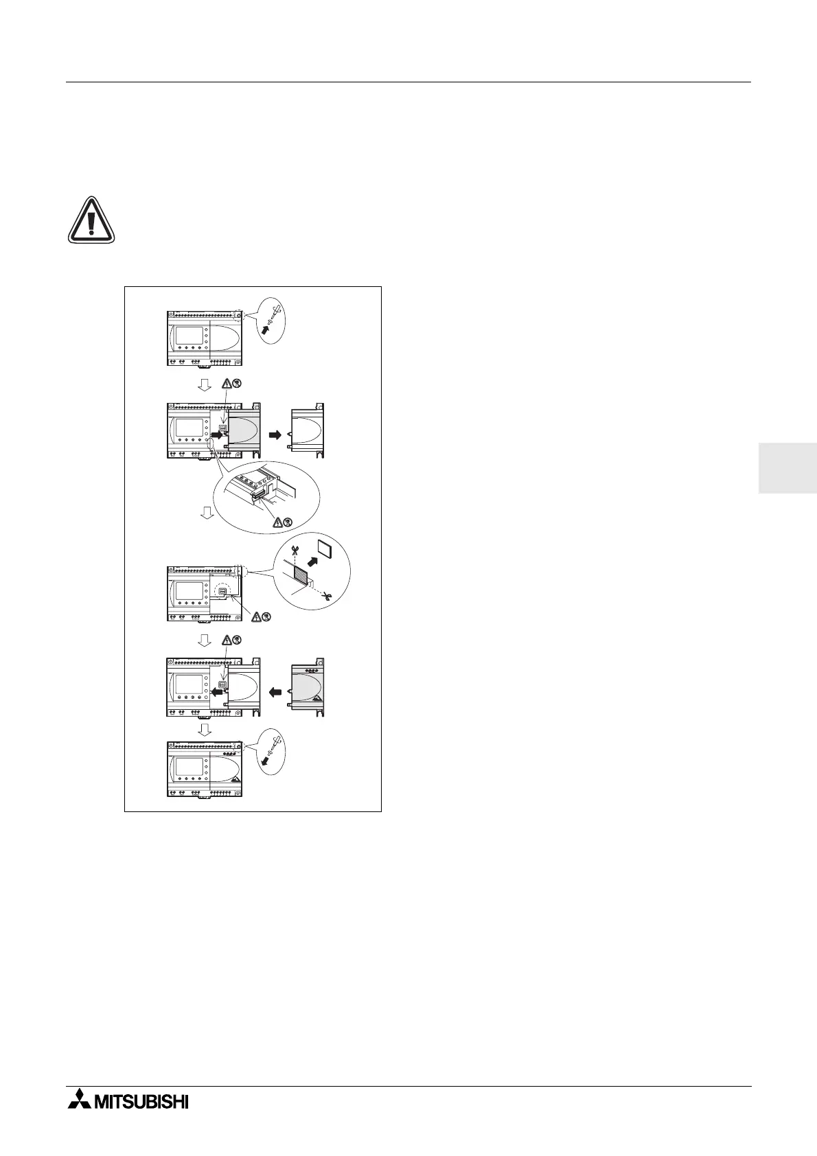
Attention!
Déconnectez toutes lesbornesd'alimentation avecd'enlever le couvercle.
Figure 9.3: Installation
1) Dévissez la vis « A »etconservez-la.
2) Retirezavecprécaution le couvercle du port
d'extension.
3) Coupez lapartie«B » del'unité de base du
contrôleur
α
.
4) Déplacez l'AL-ASI-BD sur l'unité de base.
5) Remettez lavis« A »enplaceetvissez-la en
exerçant un couple de serrage compris entre 0,4
Nm.
OUT1
OK
-
+
ESC
OUT3
9
RELAY
OUTPUT
65
OUT
8
OUT2 OUT4
7
DC INPUT
151413121110987654321(B )(A )
+-
24V D C
POW ER
AL2-24MR-D
A
AL2-24MR-D
POW ER
24V D C
-+
(A) (B) 1 2 3 4 5 6 7 8 9 10 11 12 13 14 15
DC INPUT
7
OUT4OUT2
8
OUT
56
OUTPUT
RELAY
9
OUT3
ESC
+
-
OK
OUT1
OUT1
OK
-
+
ESC
OUT3
9
RELAY
OUTPUT
65
OUT
8
OUT2 OUT4
7
DC INPUT
151413121110987654321(B )(A )
+-
24V D C
POW ER
AL2-24MR-D
A
1)
2)
3)
4)
5)
AL2-24M R-D
POW ER
24V D C
-+
(A)(B)123456789101112131415
DC INPUT
7
OUT4OUT2
8
OUT
5
OUTPUT
RELAY
9
OUT3
ESC
+
-
OK
OUT1
AL2-24M R-D
POW ER
24V D C
-+
(A)(B)12 345678 9101112131415
DC INPUT
7
OUT4OUT2
8
OUT
5
OUTPUT
RELAY
9
OUT3
ESC
+
-
OK
OUT1
6
B
 Loading...


