OUTLINE
3
1.2 Basic Configuration
1.2 Basic Configuration
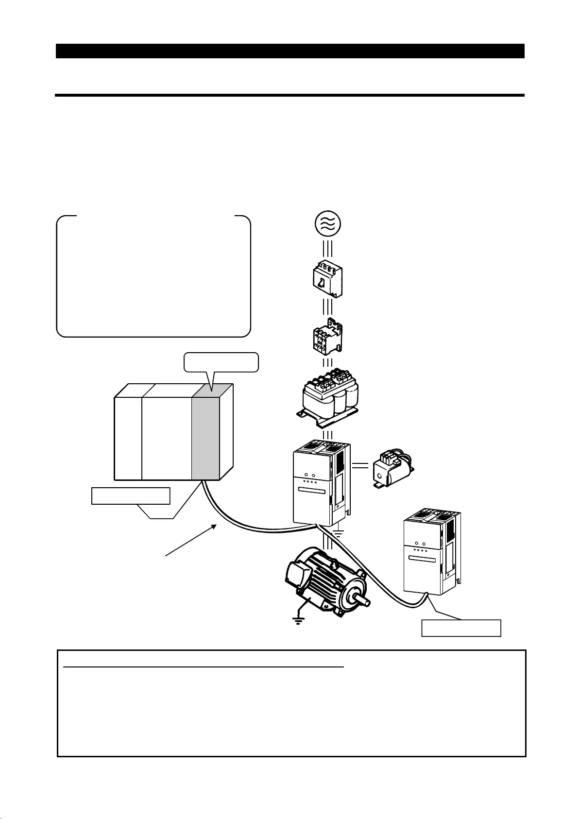
1.2.1 Basic configuration
The following devices are required to operate the inverter. Proper peripheral devices
must be selected and correct connections made to ensure proper operation. Incorrect
system configuration and connections can cause the inverter to operate improperly, its
life to be reduced considerably, and in the worst case, the inverter to be damaged.
Please handle the inverter properly in accordance with the information in each section
as well as the precautions and instructions of this manual. (For connections of the
peripheral devices, refer to the corresponding manuals.)
AJ61
BT11
CPU
(MC)
(NFB)
or
(ELB)
Ground
Ground
DC reactor
(FR-BEL)
AC reactor
(FR-BAL)
Earth leakage
circuit breaker
or no-fuse breaker
Power supply
Magnetic
contactor
Inverter
Manuals for CC-Link master station
Master station
Terminal resistor
CC-Link dedicated cable
Up to 42 inverters can be connected.
Terminal resistor
AJ61BT11/A1SJ61BT11 Control &
Communication Link System Master/
Local module User's Manual ... IB-66721
AJ61QBT11/A1SJ61QBT11 Control &
Communication Link System Master/
Local module User's Manual ... IB-66722
Power supply
Japanese Harmonic Suppression Guideline
The "harmonic suppression guideline for household appliance and general-purpose
products" issued by the Ministry of International Trade and Industries in September,
1994 applies to 3-phase 200V class inverters of 3.7kW or less. By installing the
power factor improving reactor (FR-BEL or FR-BAL), inverters comply with the
"harmonic suppression techniques for transistorized inverters (input current 20A or
less)" established by the Japan Electrical Manufacturers' Association.

 Loading...


