2.2 Wiring
INSTALLATION AND WIRING
12
2.2 Wiring
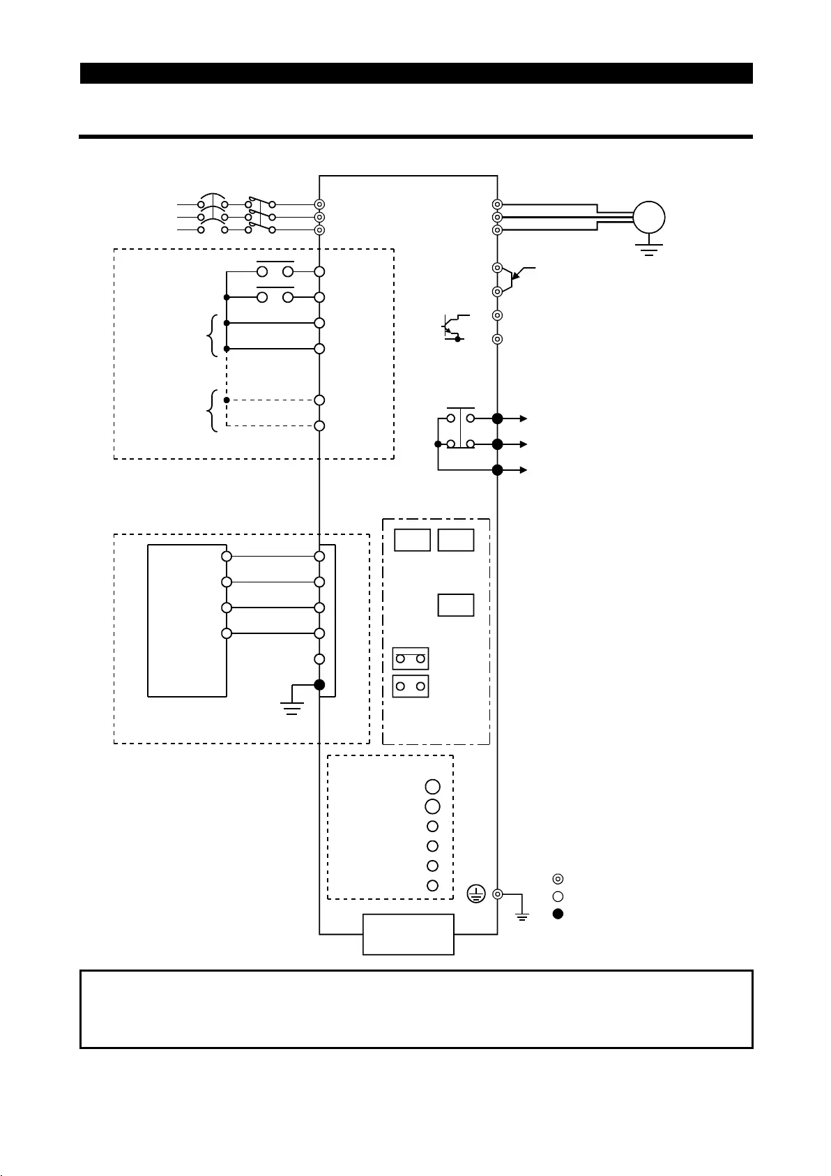
2.2.1 Terminal connection diagram
"
""
"
3-phase 200V power input
R
S
T
MRS
RES
SD
SD
P24
P24
A
B
C
U
V
W
P1
(
+
)P
PR
(
−
)N
(Note 1)
(Note 2)
(Note 2)
DA
DB
DG
FG
DA
DB
DG
SLD
SW1 SW2
SW3
SINK
SOURCE
POWER LED
ALARM LED
L.RUN LED
SD LED
RD LED
L.ERR LED
3-phase AC
power supply
NFB
Output stop
Reset
Control input signals
(no voltage input allowed)
Jumper
Remove this jumper when
using the optional power-factor
improving DC reactor.
Brake resistor connection
Motor
IM
Ground
Alarm
detection
Main circuit terminal
Control circuit input terminal
Control circuit output terminal
Ground
PU connector
(RS-485)
Sink input
commons
Source input
commons
CC-Link communication signals
PLC CC-Link
master unit
Station number
setting
Baudrate setting
Sink-source
changing
(Indicator)
(L
1
)
(L
2
)
(L
3
)
MC
SLD
SLD
Note:1. 0.1K and 0.2K do not contain a transistor.
2. Terminals SD and P24 are common terminals. Do not earth them to the
ground.

 Loading...


