OUTLINE
4
1.3 Structure
1.3 Structure
1.3.1 Appearance and structure
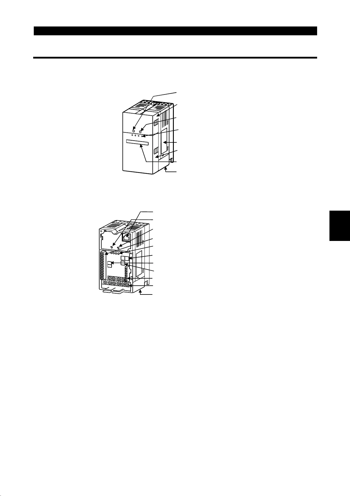
(1) Front view
POWER lamp
(yellow)
Accessory cover
ALARM lamp (red)
Operating status
indicator LEDs
Rating plate
Front cover
Capacity plate
Wirin
cover
(2) Without accessory cover and front cover
POWER lamp (yellow)
Operating status indicator LEDs
Control logic changing connector
Control circuit terminal block
PU connector*
ALARM lamp (red)
Transmission baud rate settin
switch
CC-Link terminal block
Main circuit terminal block
Wiring cover
Station number setting switches
* Use the PU connector for the FR-PU04 (option) and RS-485 communication.
1

 Loading...


