OUTLINE
5
1.3.2 Functions
Name Function
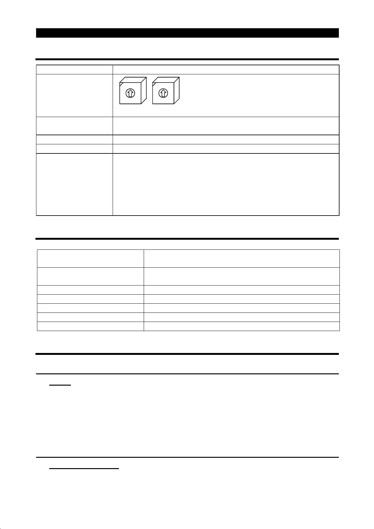
Station number setting
switches
×
10
0
9
8
7
6
5
4
3
2
1
×
1
0
9
8
7
6
5
4
3
2
1
Used to set the inverter station number
between 1 and 64.
For details, refer to page 48.
Transmission baud
rate setting switch
Switch used to set the transmission speed.
For details, refer to page 49.
POWER lamp (yellow) Lit to indicate that power is input (present).
ALARM lamp (red) Lit to indicate that a protective function is activated.
Operating status
indicator LEDs
L.RUN : Lit to indicate normal receipt of refresh data. Extinguished
when data is interrupted for some time.
SD : Extinguished to indicate that send data is "0".
RD : Lit to indicate detection of carrier in receive data.
L.ERR : Lit to indicate the communication error of the station itself.
Flickers to indicate that the switch or other setting was
changed while power is on.
1.3.3 Inverter communication specifications
Form Terminal block connection system (disconnectable from
inverter front)
Number of units connected Max. 42 units (1 station/unit occupied), other models may
also be used.
Terminal block connected 6-terminal block (M2
×
6 screws)
Cable size 0.75 to 2mm
2
Station type Remote device station
Number of stations occupied One inverter occupies one station
Connection cable CC-Link dedicated cable
1.3.4 Communication with remote devices
(1) When the CPU has automatic refresh function (example: QnA series
CPU)
Through communication with the corresponding devices using sequence ladder
logic, data is automatically transferred to/from the refresh buffer of the master
station at the execution of the END instruction to perform communication with the
remote devices.
(2) When the CPU does not have automatic refresh function (example:
AnA series CPU)
Data is transferred to/from the refresh buffer of the master station directly by
sequence ladder logic to perform communication with the remote devices.

 Loading...


