INSTALLATION AND WIRING
25
2.2.5 Connection to the PU connector
(
1
)
When connecting the parameter unit using a cable
Use the option FR-CB2
"
or the following connector and commercially available cable:
<Connection cable>
!
Connector : RJ45 connector
Example 5-554720-3, Nippon AMP,
!
Cable : Cable conforming to EIA568 (e.g. 10BASE-T cable)
Example: SGLPEV 0.5mm
×
4P, MITSUBISHI CABLE INDUSTRIES,
LTD.
<Maximum wiring length>
!
Parameter unit (FR-PU04): 20m
(
2
)
For RS-485 communication
By removing the accessory cover and using the PU connector, communication
operation can be performed from a personal computer etc.
<PU connector pin-outs>
Viewed from the inverter (receptacle side) front
8
to 1
1) SG
2) P5S
3) RDA
4) SDB
5) SDA
6) RDB
7) SG
8) P5S
Note:1. Do not connect the PU connector to a computer's LAN board, FAX modem
socket or telephone modular connector. Otherwise, the product may be
damaged due to electrical specification differences.
2. Pins 2 and 8 (P5S) provide power to the control panel or parameter unit. Do
not use these pins for RS-485 communication.
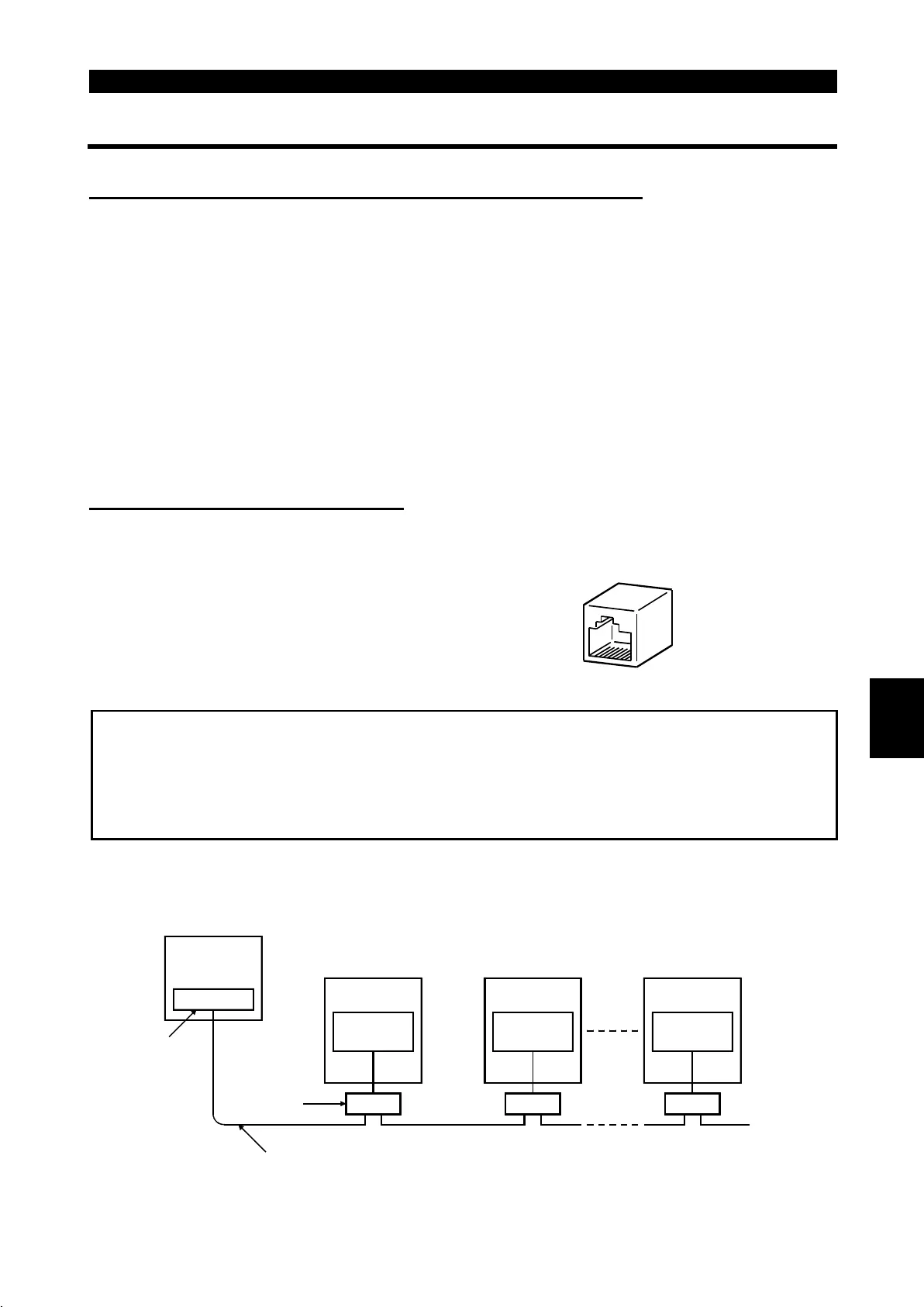
<System configuration examples>
1) When a computer having a RS-485 interface is used with several inverters
PU connector
(Note 1)
Computer
RS-485
interface/terminal
Computer
10BASE-T cable (Note 2)
Distribution
terminal
Station 1
Inverter
Station 2
Inverter
Station n
Inverter
Termination
resistor
PU connector
(Note 1)
PU connector
(Note 1)
2

 Loading...


