Keypad: 3-1
Chapter 3 Keypad
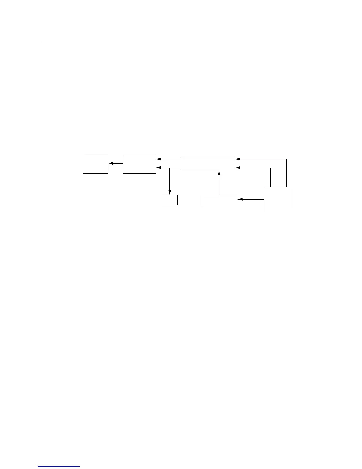
The keypad block diagram is shown in Figure 3-1. The comparator compares the voltage when any
one of the keypad row or keypad column keys is pressed. Pressing a key sends a message to the
microprocessor through the output (KEY_INT) line signifying that a key has been pressed. The
microprocessor then samples the analog to digital voltages at the keypad row and keypad column,
then makes a comparison with a map table to identify the key pressed. Once the key is identified, a
corresponding message is displayed.
The LED_EN is set by the codeplug. When the value is set to low, the LED lights up during power up.
A high codeplug setting disables this feature.
Figure 3-1. Keypad Block Diagram
40 Pin Connector
Comparator
Keypad
Button
LED
Display
18 Pin
Connector
Key_Int
Keypad Column
Keypad
Row
Data
 Loading...


