Low Band, 800 MHz, PassPort & 900 MHz Theory of Operation: Low Band Receiver 7-3
7.3 Low Band Receiver
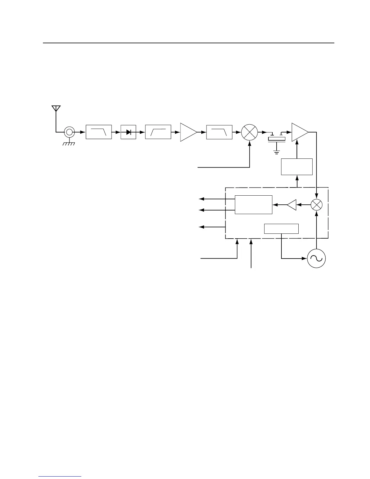
The low band receiver consists of a front end, back end, and automatic gain control circuits. A block
diagram of the receiver is shown in Figure 7-2. Detailed descriptions of these stages are contained in
the paragraphs that follow.
Figure 7-2. Low Band Receiver Block Diagram
7.3.1 Receiver Front-End
The RF signal received by the antenna is routed through the transmitter lowpass filter and antenna
switch. These circuits are described in the transmitter section.The signal next passes through a
highpass filter consisting of L501, L502, C538, C533 and C504. This filter serves to reject below
band signals and has a 3 dB corner frequency of 27 MHz.
The output of the highpass filter is connected to an RF amp consisting of Q509 and associated
biasing components. This is a BJT amplifier powered off 5 volts and has 13 dB of gain. The amplifier
drives a lowpass filter consisting of L503, L504 L507, C534, C535, C536, C537 and C515. This filter
is a pole zero design that filters off harmonic components from the RF amp. The 3 dB corner of this
filter is at 56 MHz.
The output of the lowpass filter is connected to the passive double balanced mixer consisting of
components T501, T502, and D501. After mixing with the first local oscillator up-converted to a
109.65 MHz IF signal.
The IF signal coming out of the mixer is transferred to the crystal filter (FL301) through a resistor pad
(R507, R508 and R509) and a diplexer (C516 and L508). Matching to the input of the crystal filter is
provided by L301, L302, C301 and C302. The 3 pole crystal filter provides the necessary selectivity
and intermodulation protection.
Demodulator
Synthesizer
Crystal
Filter
Mixer
RF
Amp
IF
Amp
Highpass
Filter
Lowpass
Filter
ntenna
First LO
from FGU
Recovered Audio
Squelch
RSSI
SPI Bus
17.0 MHz
Reference Clock
Secon
LO VC
RFJack
Lowpass
Filter
Antenna
Switch
AGC
Processing
IF IC U303

 Loading...


