9-474 900 MHz Circuit Board/Schematic Diagrams and Parts List (PCB 8471203M01)
RXFE Top Shield Mixer Shield
SHIELD
SH301
SHIELD
SH303
0.75V
2.95V
R306
5.6K
RX_IN_1_FE
3
1
C300
12pF
CR300
2
47pF
C316
18nH
L301
C302
0.5pF
1
OUT
2
FL300
45J78
GND
3
INRX_IN
1
3
68pF
C318
-53 dBm Note 1, Note 2
Q301
68pF
C306
12nH
L302
C307
68pF
R309
2.7K
C303
68pF
C310
68pF
27K
R307
C317
0.1uF
R312
68
5.6K
R310
R314
5.6K
Q302
0.1uF
C304
-41 dBm Note 1, Note 2
C308
1.2pF
R5
L304
18nH
R5_3_FER5_2_FE
3
GND
1
IN
2
OUT
45J78
FL301
C305
4pF
filter
39nH
L303
NU
1.3pF
C320
NU
8
RF
U301
1
GND1
GND2
GND3
GND4
GND5
3
4
6
7
2
IF
5
LO
3.3pF
6.8nH
C321
L311
R5
3.6K
R323
560
R324
C311
68pF
C313
68pF
3.15V
3
2
R326
47
47nH
L308
L307
27nH
C314
68pF
0 dBm @752.2MHz Note 1
0.75V
68pF
C309
100nH
L309
68pF
C319
RX_LO_1_FE
NU
1
HP415
Q304
30K
R325
R328
3.3nH
15K
L310
RX_LO
5.1pF
C315
39
R327
+6.5 dBm @ 752.2MHz Note1
-50.3 dBm @ 109.65MHz Note 1
LO_TEST
LO_TEST_1_FE
IF_1_FE
0
L305
IF
NU
10pF
C322
10pF
C324
NU
1
R320
51
2
30pF
C312
L306
150nH
51
R322
2
1
NU
C323
0
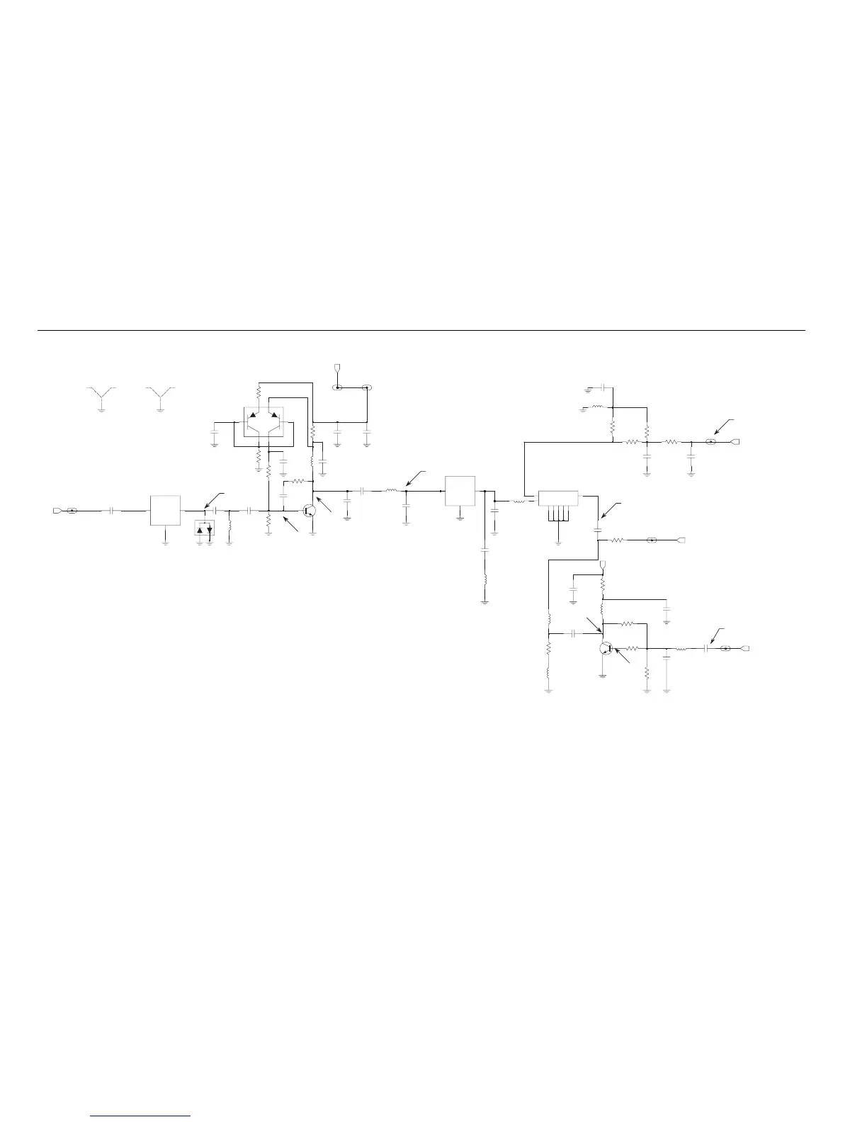
Notes:
1. Measured using high impedance probe.
2. Measured with -50dBm 861.85MHz RX signal at the antenna input.
3. Measured with no RX signal at the antenna input.
Figure 9-279. 900 MHz Receiver Front End Schematic Diagram

 Loading...


