VHF Theory of Operation: Receiver (for models with PCB 8486473Z04) 6-5
Radio signal strength indicator, RSSI, a voltage signal, is used to drive Q3301 to saturation i.e.
turned on. RSSI is produced by U3220 and is proportional to the gain of the RF amplifier and the
input power to the radio.
Resistors R3304 and R3305 are voltage dividers designed to turn on Q3301 at certain RSSI levels.
In order to turn on Q3301 the voltage across R3305 must be greater or equal to the voltage across
R3324, plus the base-emitter voltage (Vbe) present at Q3301. Capacitor C3209 is used to dampen
any instability while the AGC is turning on. The current flowing into the collector of Q3301, a high
current gain NPN transistor, will be drawn through the PIN diode to turn it on. Maximum current
flowing through the PIN is limited by the resistors R3316, R3313, R3306 and R3324. C3326 is a
feedback capacitor used to provide some stability to this high gain stage.
An additional gain control circuit is formed by Q3201 and its associated circuitry. Resistors R3206
and R3207 are voltage dividers designed to turn on Q3201 at a significantly higher RSSI level than
the level required to turn on PIN diode control transistor Q3301. In order to turn on Q3201 the
voltage across R3207 must be greater or equal to the voltage across R3208, plus the base-emitter
voltage (Vbe) present at Q3201. As current starts flowing into the collector of Q3201, it reduces the
bias voltage at the base of IF amplifier transistor Q3200 and in turn, the gain of the IF amplifier. The
gain can be controlled in a range of -30 dB up to +10 dB.
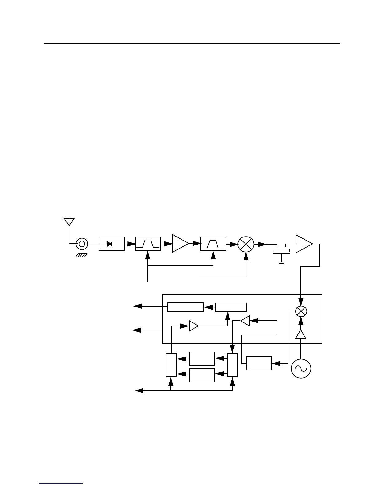
6.3 Receiver (for models with PCB 8486473Z04)
Figure 6-3. VHF Receiver Block Diagram
Crystal
Filter
Mixer
Varactor
Tuned Filter
RF Amp
Varactor
Tuned Filter
Pin Diode
Antenna
Switch
RF Jack
Antenna
Control Voltage
from ASFIC
First LO
from VCO
Second LO
IF Amp
455kHz
Filter
Switch
455kHz
Filter
455kHz
Filter
Switch
Demodulator
RSSI
Limiter
Recovered Audio
BW SEL
U3220

 Loading...


