3-2 Keypad: Controller Board
3.1 Controller Board
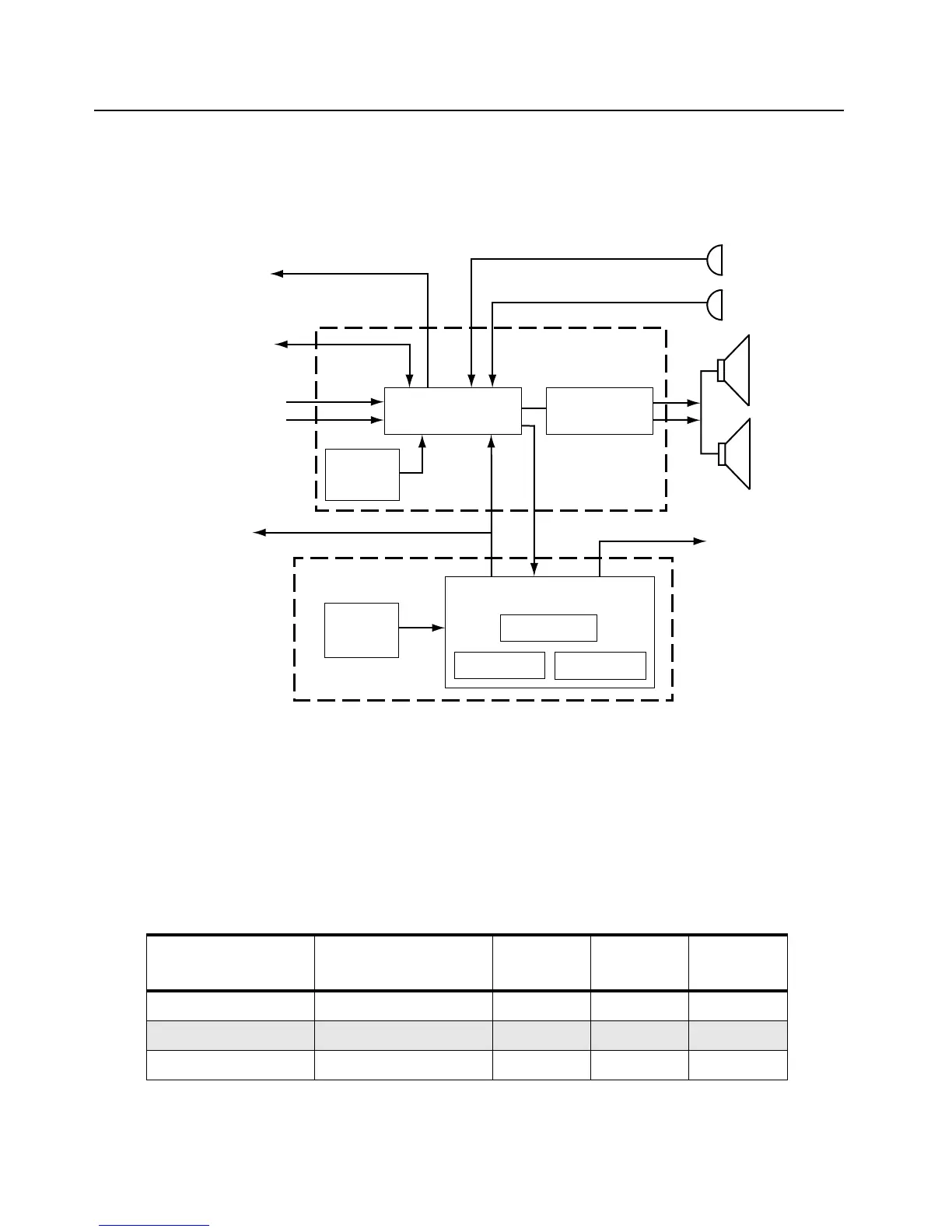
The controller board is the central interface between the various radio functions. It is separated into
MCU digital and audio/signalling functions as shown in Figure 3-2.
Figure 3-2. Controller Block Diagram
3.1.1 MCU Digital
The digital portion of the controller consists of a microcontroller and associated EEPROM, RAM, and
ROM memories. Combinations of different size RAM and ROM are available to support various
application software. RAM supports 8KB and 32KB sizes. ROM supports 128KB, 256KB, and 512KB
sizes. Table 3-1 lists the ROM, RAM and EEPROM requirements for different radios.
Table 3-1. Radio Memory Requirements
PROTOCOL FEATURE LEVEL ROM (KB)
EXT RAM
(KB)
EEPROM
(KB)
AA,DU 2 or 3 128 - 8
AA,DU 6 128 - 16
CK, GB, GE, FC - 512 32 16
External
Microphon
Internal
Microphone
Extern
Speak
Intern
Speak
SCI to Side
Connector
Audio/Signalling
To Synthesizer
Mod Out
6.8 / 17.0 MHz
eference Clock
rom Synthesizer
Recovered Audio
Squelch
SPI
MCU Digital
RAM
EEPROM
ROM
Microcontroller
ASFIC
3.3V
Regulator
(Vdda)
3.3V
Regulator
(Vddd)
Audio Power
Amplifier/Filter
CLK
o RF Board

 Loading...


