2202L5JE-DA-C5-N_2015.05.
5 Maintenance and Inspection
Compound 2-stage Screw Compressor 5.5 Reassembly
1612LSC Speed Increaser Type
5-57
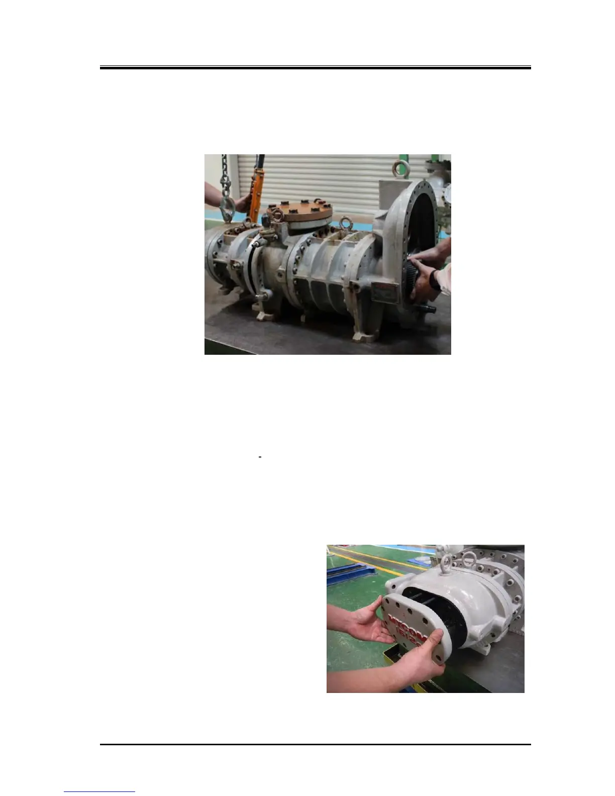
f) Lift the high-stage by using lifting tools until it is slightly off the work bench, and move it toward the
low-stage.
At this moment, on the low-stage, slightly move the M rotor shaft in both directions, so that the gear
coupling assembly will fit smoothly (picture below).
g) After the gear coupling is engaged, press the high-stage block parallel with the rotor shaft. For both
upper and lower sides, gradually and evenly tighten, temporarily, the hexagon socket head cap
screws [18-2] that are set in the bolt holes, each hole located one or two holes apart from the left or
right alignment pin, until the high-stage and low-stage flange surfaces come into contact.
h) After the flange surfaces come into contact, slightly loosen the four hexagon socket head cap
screws, which have been temporarily tightened, and then drive in the left and right alignment pins.
i) Tighten the hexagon socket head cap screws to the specified torque (90 N·m). The lower bolts
should be tightened on the special
stand, which was used during disassembly.
j) Turn the low-stage M rotor (use of a jig for rotating the rotor is helpful), and check that it rotates
properly.
5.5.8 Balance Piston Cover
Attach the balance piston cover gasket [23] on the
high-stage suction cover flange while paying
attention to the oil hole of the gasket.
It is no problem which assembly work is fast,
attaching balance piston cover to main rotor casing
or combining low-stage and high stage blocks.
Attaching Balance Piston Cover
 Loading...
