2202L5JE-DA-C5-N_2015.05.
2 Compressor Specifications and Structure
Compound 2-stage Screw Compressor 2.6 Gas and Oil Flow
1612LSC Speed Increaser Type
2-10
2.6 Gas and Oil Flow
The screw compressor’s compression process is
described earlier in this manual.
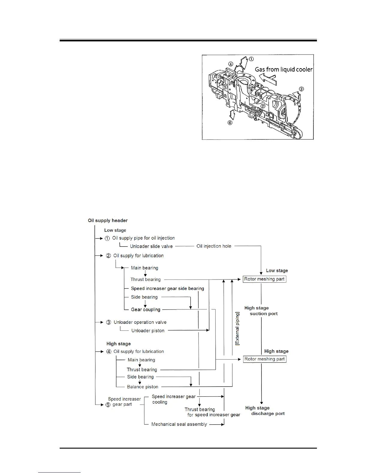
Gas for the compound speed increaser type 1612LSC
compressor passes from the evaporator and through
the suction strainer and check valve, and is sucked
into the center part of the compressor ①, and it is
compressed at the low-stage ② .Then the
compressed gas is discharged at ③. ③ and ④ are
connected by piping through which gas used for super
cooling is mixed in from the liquid cooler.
Lubricating oil injected at the low-stage is, while kept
mixed with gas, suctioned from ④ into the high-stage.
After being compressed at ⑤, the gas mixed with
lubricating oil is discharged from ⑥ to the oil separator, and then sent to the condenser.
The oil is cooled even without intermediate gas cooling, so the high-stage discharge temperature can
be maintained at below 90 °C.
Oil Supply Route
Lubricating oil is split into 4 flows as shown in Figure 2-12, and after providing lubrication, it is
mixed with discharge gas and leaves the compressor. In standard configurations, oil injection is not
performed at the high-stage.
Figure 2-12
1612LSC Speed Increaser Type Oil Supply Route
Figure 2-11 Gas Flow
 Loading...
