2202L5JE-DA-C5-N_2015.05.
2 Compressor Specifications and Structure
Compound 2-stage Screw Compressor 2.5 Mechanisms
1612LSC Speed Increaser Type
2-6
2.5 Mechanisms
2.5.1 Basics of the Screw Compressor
The screw compressor is a positive displacement rotary compressor.
As shown in Figure 2-3 Compressor Mechanism, the refrigerant (gas) is continuously compressed by
changing the volume between the casing and the male and female meshed screw rotors, which have
different profiles.
The rotor with 4 protruding lobe sections is called the M rotor (male rotor), and the rotor with 6 lobe
depressions is called the F rotor (female rotor). Throughout this manual they are referred to as the M
rotor and F rotor.
The compressor M rotor shaft is driven by the two-pole or four-pole motor via the speed increaser gear.
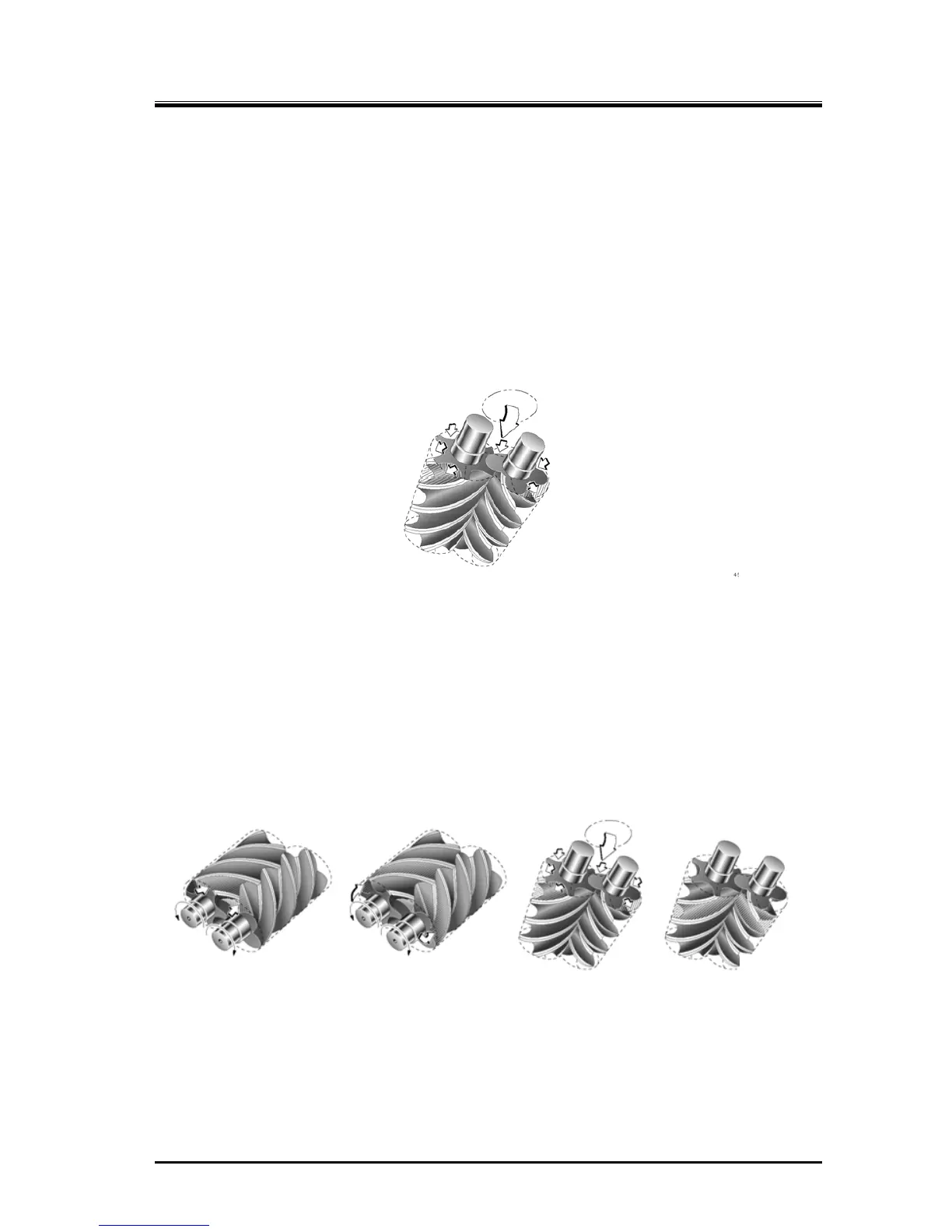
Figure 2-3 Compressor Mechanism
2.5.2 Suction Process
As shown in Figure 2-4 Suction Process, the rotors’ different profiles mesh together. Also the volume
enclosed between the M and F rotor lobes and compressor casing increases from the suction side as
the rotors turn.
As rotations continue, at a certain point the volume reaches its maximum, the rotors start to trap the gas
between the lobes and compressor casing thereby isolating the gas from the suction port.
Figure 2-4 Suction Process
 Loading...
