2202L5JE-DA-C5-N_2015.05.
5 Maintenance and Inspection
Compound 2-stage Screw Compressor 5.4 Disassembly and Inspection
1612LSC Speed Increaser Type
5-15
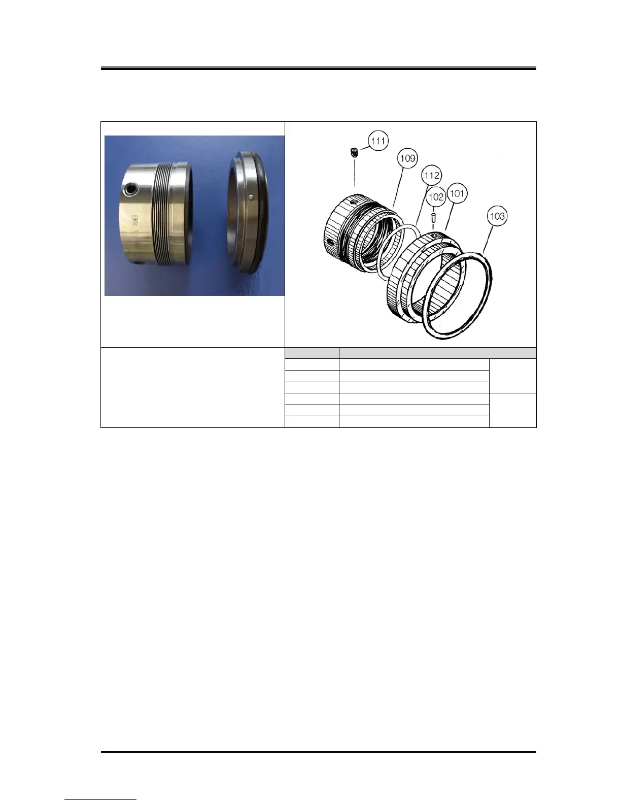
5.4.1 Shaft Seal Block
P/N Part name
101 Mating ring
Mating
ring
102 Insert lock pin
103 O-ring
109 Seal collar
Rotating
ring
111 Seal collar set screw
112 O-ring
Figure 5-2 Details of BBSE Type Mechanical Seal Assembly
5.4.1.1 Disassembly
a) Of the eight hexagon socket head cap screws [53] on the seal cover [51], remove six screws leaving
two diagonally opposite screws.
b) Slowly loosen the remaining two screws by turns so that they stay even. After a certain amount of
loosening, the seal cover of the mechanical seal will be pushed by the spring and a gap will appear.
A gap will not appear if the gasket is stuck. In that case, push the seal cover by screwing the M8
eyebolts into the seal cover’s service holes.
c) Use a container to catch the oil that will flow out through the gap.
d) Pull out the seal cover keeping it parallel with the shaft (rotor axis). The mating ring inside the seal
cover is attached with an O-ring [103]. Ensure that the mating ring and shaft do not come into
contact causing damage.
e) Remove the O-ring [49] between the seal cover and the seal retainer [48].
f) After removing the seal cover, wipe clean and inspect the axis surface. If there are scratches, use
fine sandpaper to smooth them over. This is done to prevent damage to the internal O-ring when
pulling out the mechanical seal.
g) Loosen the set screws [111] of the seal collar [109] by turning them three times.
For 1612LSC type compressors, remove the plug on the speed increaser gear casing cover and
loosen the set screws through the plug hole with a hexagonal
wrench. At this time, do not remove
the set screws, but leave them so that the tips are below the surface of the seal collar. There are
two set screws separated by 90°.
 Loading...
