2202L5JE-DA-C5-N_2015.05.
5 Maintenance and Inspection
Compound 2-stage Screw Compressor 5.4 Disassembly and Inspection
1612LSC Speed Increaser Type
5-35
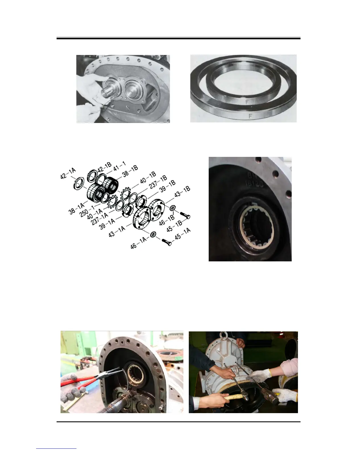
Pulling Out Thrust Bearing Outer race Spacer and Alignment Spacer
5.4.13.2 Disassembly of Low-stage Thrust Bearing Block
Figure 5-11 Low-stage Thrust Bearing Block
a) The roller bearing [185] outer race supporting the speed increaser dear spindle shaft end is
installed in the upper part of the low-stage bearing head (above picture). To remove this roller
bearing outer race, remove the internal snap ring [186] retaining the outer race, first (following
picture to the left).
b)
Next remove the plugs from the two holes on the back of the bearing head. Through the holes, insert
steel rods or similar tools. Strike the rods on their ends alternately and little by little to force out the
roller bearing (following picture to the right).
* The roller bearing outer race may be removed prior to the removal of the thrust bearing gland as
shown in the picture to the left.
 Loading...
