2202L5JE-DA-C5-N_2015.05.
5 Maintenance and Inspection
Compound 2-stage Screw Compressor 5.4 Disassembly and Inspection
1612LSC Speed Increaser Type
5-28
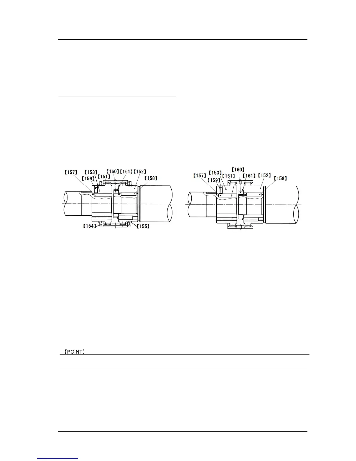
5.4.8 Gear Coupling
The gear coupling, which is used as a power transmission means, is divided into the high-stage and the
low-stage blocks, with each block attached to the corresponding M rotor shaft, and these two blocks are
directly connected by a drive sleeve.
Gear coupling mechanism of 1612**C models
In January 1979, the coupling method was changed from the initial type (coupling hub is directly
connected using hexagon head screws) to the method using coupling hub and sleeve. This method
was used for a long time.
However, the anti-falling method of the drive sleeve was modified in February 2011 as the design
modification. While the old couplings have stoppers on both outer ends of the drive sleeve, the
stoppers are placed on the inside of the drive sleeve after the design modification (compatible with the
old type).
After this design modification, the drive sleeve stopper [154] and snap ring [155] are no more used.
.
Gear coupling assembly comprising Gear coupling assembly comprising
151, 152, 153, 154*2, 155*2 and 159. 151, 152, 153 and 159.
Figure 5-7 Former Method Figure 5-8 New Method
(Used Until Design Change in Feb. 2011) (Used After Design Change in Feb. 20101
5.4.8.1 Disassembly
a) Drive sleeve [151] can be removed with hands when the high-stage and low-stage are separated.
b) On the high-stage (driven) side, loosen the set screw [159] of the key [157] attached on the driven
hub [153], and then remove the driven hub. As it is clearance-fitted, it can be removed easily.
c) On the low-stage side, unbend the lock washer tooth [161] and loosen the lock nut [160] to remove
the drive hub [152].
d) Two screw holes are provided on the drive hub. Screw in M8 eye bolts, and pull out the drive hub.
As it is clearance-fitted, it can be removed easily.
For the set screw [159], MAYEKAWA recommends a knurled cup point locking screw with an
anti-loosening coating on the screw.
5.4.8.2 Inspection
Check the hub and sleeve for possible deformation of the gear teeth and wear on each tooth flank.
If any defect is found, replace the whole gear coupling assembly. Also, investigate cause(s) of the
defect.
 Loading...
