2202L5JE-DA-C5-N_2015.05.
5 Maintenance and Inspection
Compound 2-stage Screw Compressor 5.4 Disassembly and Inspection
1612LSC Speed Increaser Type
5-19
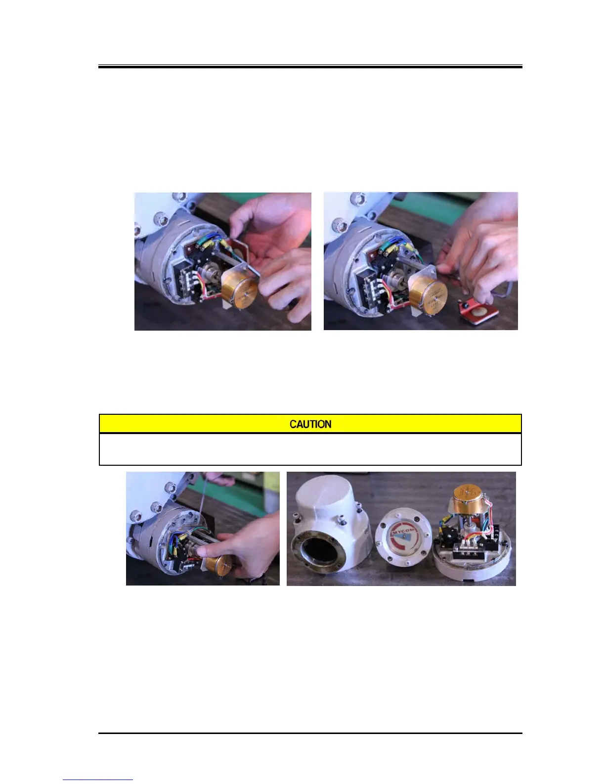
When removing entire unloader indicator assembly, with the wiring left as it is
a) After the disassembly in the previous section, the internal potentiometer [129], micro-switches
[125], and micro-switch base plate [121] with micro-switch cam [127] attached can be removed.
b)
Micro-switch base plate is fastened to the unloader cover with two hexagon socket
head cap screws [122]. Since the one screw of them is hidden under the connector
support [144], remove two hexagon socket head cap screws [145] and the connector
support (following picture to the left).
c)
Then remove two hexagon socket head cap screws fastening the micro-switch base plate
(above picture to the right).
d) Micro-switch cam [127] is secured to the indicator cam [77] by a set screw [128]. Turn the
micro-switch base plate to easy direction for the work, and then loosen this set screw to free
the micro-switch cam (following picture to the left).
When you remove the set screw [128] from the micro-switch cam, it is easy to
lose the screw. Leave it only to loosen.
e) Now, it is possible to remove the indicator assembly as is by pulling in the axial direction.
5.4.2.2 Inspection
Since the unloader indicator block is removed as assembly and its inspection and adjustment is often
performed after reassembling and recovering the compressor, the inspection procedure is described in
Section 5.7 "Reassembly" in this chapter. Refer to Section 5.5.15 "Unloader Indicator".
 Loading...
