2202L5JE-DA-C5-N_2015.05.
2 Compressor Specifications and Structure
Compound 2-stage Screw Compressor 2.3 Compressor Specifications
1612LSC Speed Increaser Type
2-2
2.3 Compressor Specifications
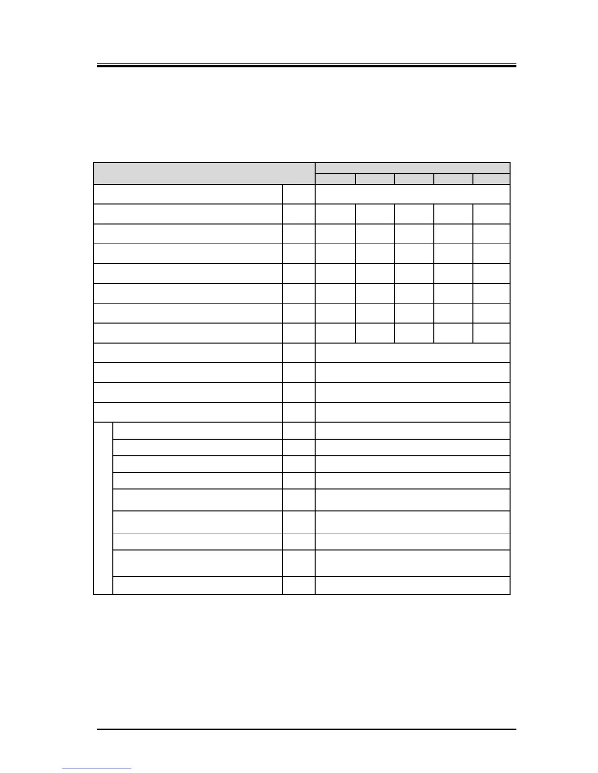
2.3.1 Standard Specifications
Table 2-1 1612LSC Speed Increaser Type Screw Compressor Specifications
Item
1612LSC Speed Increaser type
52 62 53 63 54
Product mass kg 560
Applied frequency Hz 50 60 50 60 50
Motor Poles - 4P 4P 2P 2P 2P
Speed increaser gear ratio - 1.809 1.809 1.220 1.220 1.472
Male rotor rotational speed min
-1
2610 3150 3610 4350 4350
Female rotor rotational speed min
-1
1740 2100 2407 2900 2900
Low-stage swept volume m
3
/h 551 665 762 918 918
High-stage swept volume m
3
/h 174 210 241 290 290
Applied refrigerant - Ammonia, Hydrofluorocarbon, other
Design pressure MPa 2.6
Capacity control range (Actual load) % 10 to 100
Rotation direction - Crockwise viewed from motor
Connection pipe size
Suction flange low-stage - MYCOM 125A (5″)
Discharge flange low-stage
- MYCOM 80A (3″)
Suction flange high-stage - MYCOM 80A (3″)
Discharge flange high-stage
-
MYCOM 65A (2½″)
Journal lubricating oil supply
(low-stage)
- Rc1/2
Journal lubricating oil supply
(high-stage)
- Rc3/8
Oil injection lubricating oil supply
- Rc3/8
Mechanical seal and speed increaser
gear lubricating oil supply
- Rc1/4
Capacity control - Load: Rc1/4, Unload: Rc3/8
In this manual unless otherwise noted, pressure units MPa represents the gauge pressure.
For usage temperature ranges and pressure ranges, refer to Section2.3.2 “Operation Limits”.
 Loading...
