2202L5JE-DA-C5-N_2015.05.
5 Maintenance and Inspection
Compound 2-stage Screw Compressor 5.5 Reassembly
1612LSC Speed Increaser Type
5-61
5.5.10 Installation of Speed Increaser Gear Casing to Low-stage
Bearing Head
a)
Start this operation after checking the bearing head assembly for the following point:
The bearing head has two oil holes, one for lubricating the speed increaser gear and the other for
lubricating the roller bearing of the speed increaser gear spindle. As each of the oil holes has the oil
flow control throttle [196-2] screwed inside, check that the throttle is not clogged.
b)
Apply oil to both sides of the speed increaser gear casing gasket [170] and attach it.
Carefully install the speed increaser gear casing gasket [170] with its sides
directed correctly. The gasket has an oil hole for the side bearing in the speed
increaser gear casing on one side, although the gasket is symmetrically shaped
and the bolt holes in it are also symmetrically arranged.
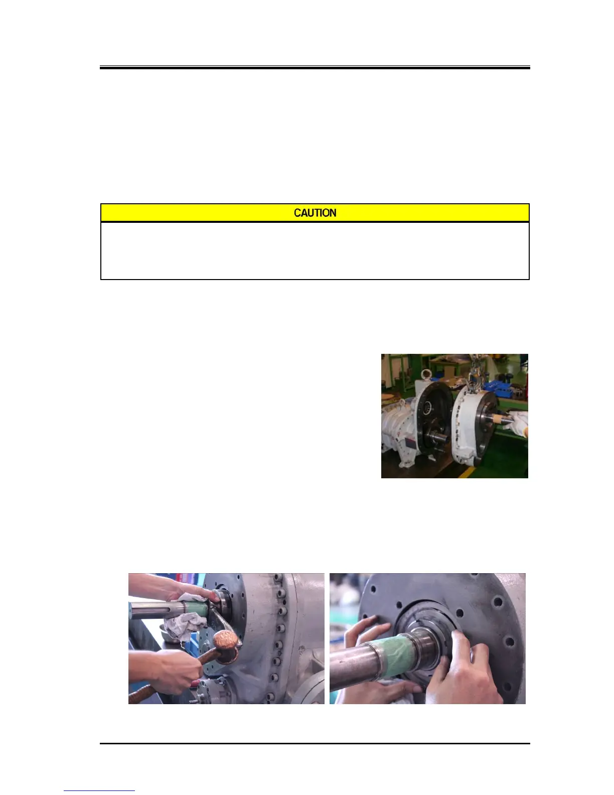
c)
Install the speed increaser gear casing assembly to the low stage bearing head. For the sake of
safety, it is strongly recommended to perform this operation by suspending the speed increaser
gear casing assembly with a proper means like a chain block.
By holding the end of the spindle protruding from the speed increaser gear casing assembly, move
the assembly until the roller bearing outer race on the bearing
head engages with the roller bearing inner race on the spindle
and then press on the assembly in the axial direction (right
picture).
Do this operation while turning the spindle in both directions
by holding its end a little to make the speed increaser drive
and driven gears engage with each other.
d)
When the flanges of both blocks come into contact, align
them and temporarily tighten two hexagon socket head cap
screws [18-1] in a left-right symmetry way. Then, drive
alignment pins [19-1] into the low-stage bearing head.
e) Fasten the hexagon socket head cap screws [18-1] in turn and evenly to the specified torque.
f) Remove the temporary thrust bearing holding jig to fix the thrust bearing inner race onto the speed
increaser gear spindle, insert the lock washer [194], torsional slip washer [237-1C] and the lock nut
[193]. Then, tighten the lock nut to the specified torque or within the specified range of the tightening
angle (following picture to the right) by using the lock nut wrench.
Also tightening the lock nut in this step should change the position of applying the lock nut wrench to
avoid uneven tightening (refer to Section 5.5.6 b) [POINT]).
 Loading...
