2202L5JE-DA-C5-N_2015.05.
5 Maintenance and Inspection
Compound 2-stage Screw Compressor 5.4 Disassembly and Inspection
1612LSC Speed Increaser Type
5-27
5.4.7 Separating High-stage and Low-stage
Separate the high-stage and low-stage when
inspect the high-stage thrust bearing block or pull
out each stage’s rotor is required.
Structurally, it does not matter even if separated
at the first step of disassembly.
Separating High-stage and Low-stage
5.4.7.1 Disassembly
a) As explained in Section 5.3.5 of this chapter, put the compressor on a special table and remove the
bolts from the lower side. Then, remove the remaining hexagon socket head cap screws [18-2].
At this moment, the high-stage of the compressor is spaced apart the work bench. Brace the
high-stage with a rectangular piece of wood or the like to prevent it from falling when disassembled.
b) Drive alignment pins [19-2] into suction cover [5-1].
c) Since the bearing head [11-2] and suction cover are stuck together with the gasket [17], screw the
previously removed bolts [18-2] into two jacking threaded holes on the bearing head to push out the
suction cover evenly.
Do not insert a screwdriver or chisel into the gap.
d) On the M rotor axis there are power transmission gear couplings [151 to 161].
Move the casing in parallel with the axis to separate the driving side and the driven side in the axial
direction.
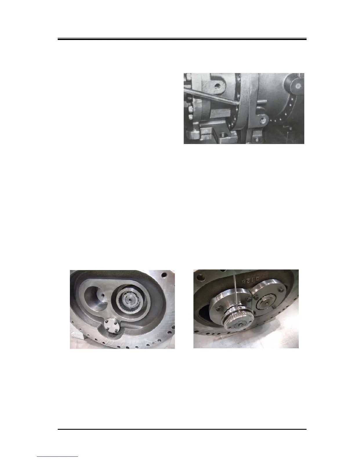
Low-stage After Separation Removing Driven Hub
* Above pictures are gear coupling before the design modification of February, 2011.
 Loading...
