2202L5JE-DA-C5-N_2015.05.
2 Compressor Specifications and Structure
Compound 2-stage Screw Compressor 2.5 Mechanisms
1612LSC Speed Increaser Type
2-9
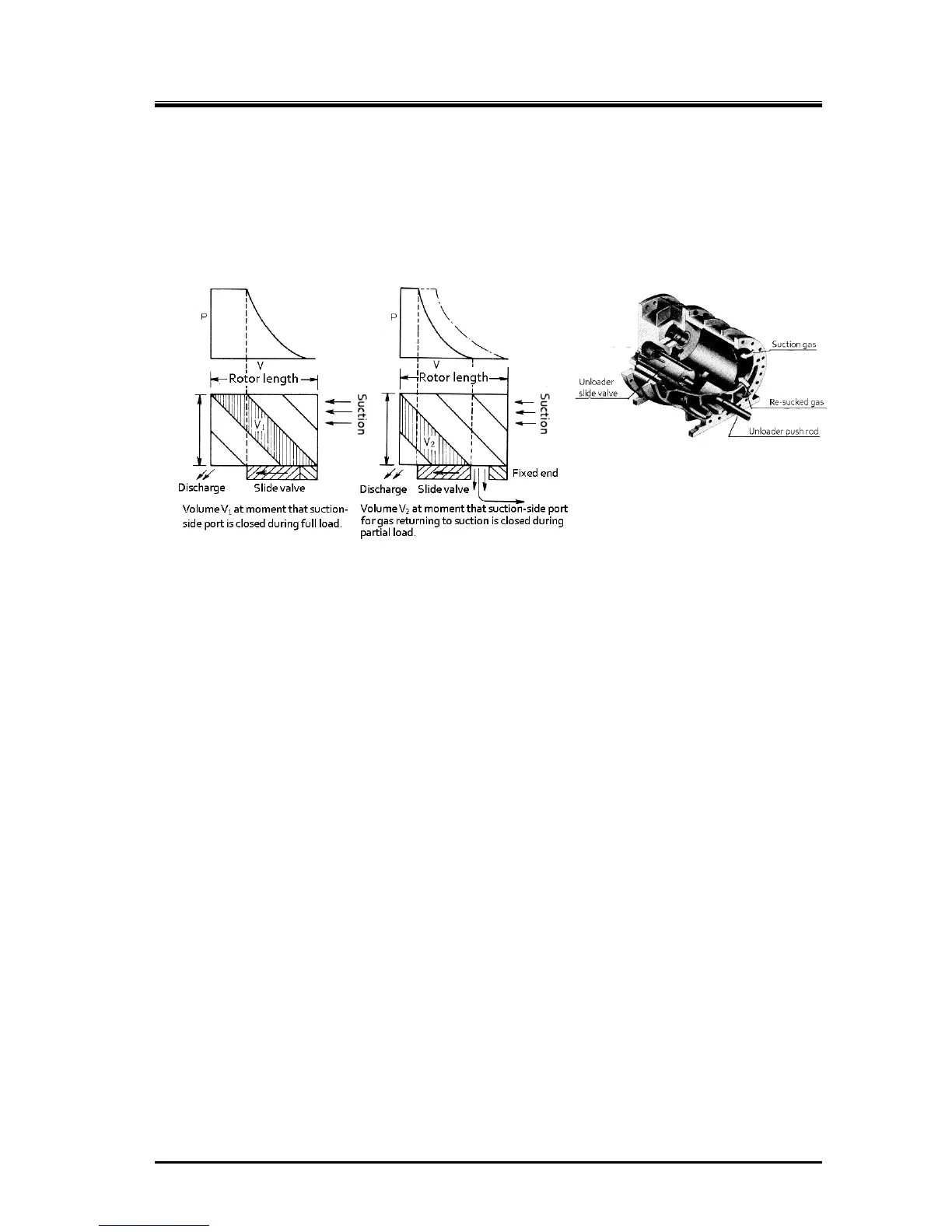
2.5.6 Capacity Control Mechanism
The capacity control structure involves the moving of a slide valve, bypassing suction gas just before
compression on the suction side, which shortens the portion of the rotor used for compression. The
slide valve is at the bottom of the casing where the rotors mesh together, and is constructed to move
parallel to the rotor’s axis. This movement is changed by a cam mechanism into rotation movement,
and as the position (capacity control ratio) is indicated externally, the electrical resistance value
changes to provide feedback to the automatic control circuit.
Figure 2-9 Capacity Control Mechanism
The 1612LSC speed increaser type has capacity control on the low-stage block only.
2.5.7 Bearings and Balance Piston
For the load created on the rotor perpendicular to the axle, a white metal-lined sleeve-type bearing is
used. The bearing uses surface fitted ball bearings with angular contact for loads along the axis
direction.
In particular, axial load for the M rotor, which has one type of helical gear, is comparatively larger than
that of the F rotor because of the thrust load from discharge pressure. This load for the M rotor is
reduced by the use of a thrust bearing, along with a balance piston providing opposing hydraulic
pressure.
2.5.8 Shaft Seal
To prevent refrigerant gas and oil leakage, a reliable mechanical seal assembly is used for the shaft
seal of the speed increaser gear spindle.
Mechanical seal assembly is mainly composed of "rotating ring" installed on the rotor shaft and
"stationary ring" installed in the seal cover. Rotating ring rotates with the shaft, and slides each other
with the stationary ring while maintaining a micron class gap. The sliding each other place is called as
the sliding surface.
As an example, for the BBSE (Balanced Bellows Single Seal)-type, which is a standard seal currently in
use, the fixed ring (mating ring) is cast iron, and the rotating ring is carbon, with an O-ring for the
packing.
Figure 2-10 Slide Valve in the
Rotor Casing
 Loading...
