2202L5JE-DA-C5-N_2015.05.
5 Maintenance and Inspection
Compound 2-stage Screw Compressor 5.5 Reassembly
1612LSC Speed Increaser Type
5-58
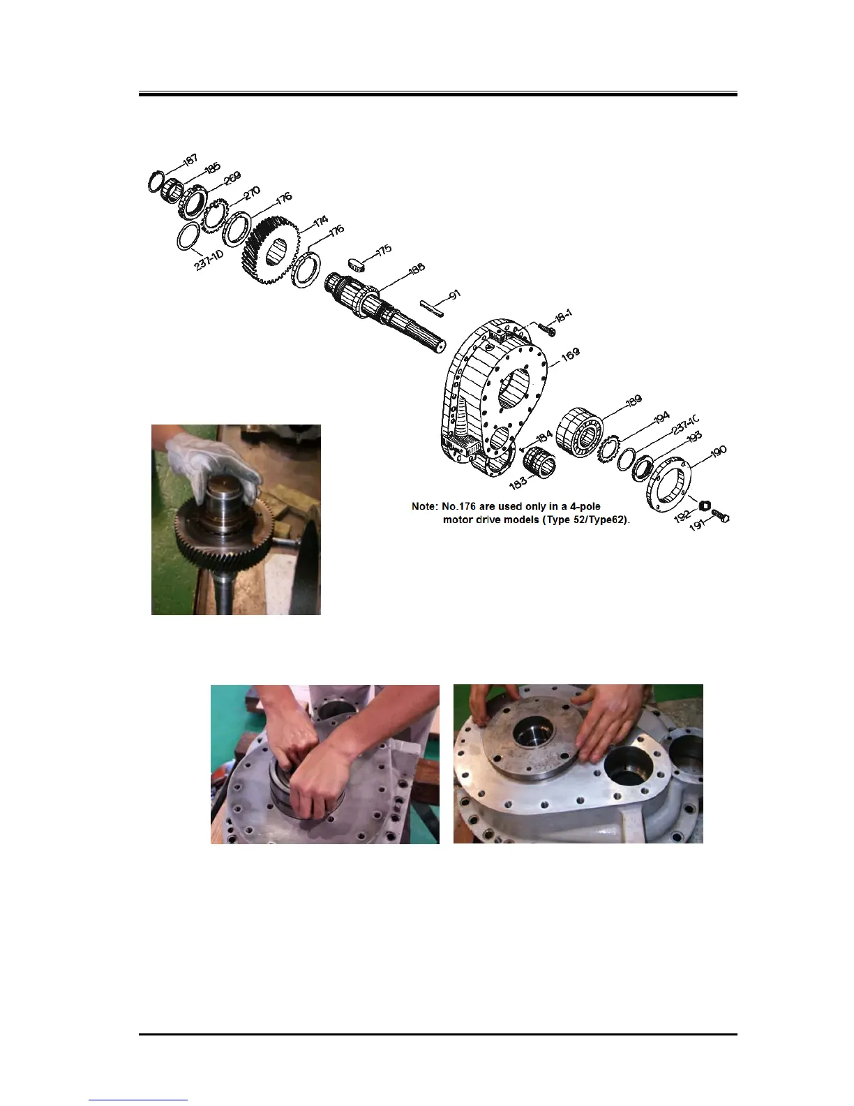
5.5.9 Speed Increaser Gear Block
a) In case of disassembling the speed increaser drive gear [174] and speed
increaser gear spindle [188], attach the shaft key [175] on the gear
spindle and install the speed increaser drive gear on the spindle.
Tighten the speed increaser drive gear by fastening the lock
nut [269] with the lock washer [270] and torsional slip
washer [237-1D].
Bend the tooth of the lock washer to prevent
the lock nut from rotation.
* In the -52 and -62 models
which are equipped with a speed
increaser gear system and driven by
a 4-phase electric motor, the speed
increaser drive gear has spacers [176]
on both the front and rear sides.
Figure 5-21 Speed Increaser Gear Casing Block
b)
Heat the inner race of the roller bearing [185] using a bearing
heater (set at 90°C), as shown in the left picture, fit it on the
speed increaser gear spindle and install the external snap ring
[187] to secure the inner race.
c)
Install the thrust bearing [189] for the speed increaser gear spindle into the speed increaser gear
casing [169] (following picture to the left). This bearing is a face-to-face angular contact ball bearing
as same as the thrust bearings for M rotors and F rotors.
d)
Temporarily hold the thrust bearing by installing a jig in the place where the thrust bearing gland
[190] is to be installed (above picture to the right).
The jig serves for holding the thrust bearing inner race to prevent it from being forced out toward the
speed increaser gear casing cover [171] when the speed increaser gear spindle is installed.
The reason of using the jig in this step instead of the thrust bearing gland is as follows.
* The thrust bearing gland cannot be used for the above purpose as the gland has no part to hold
the inner race (because if the gland had a part for holding the inner race, the part would block the
motion of the speed increaser).
Install the jig by finger-tightening the four hexagon head bolts. Do not use any tool to tighten them.
 Loading...
