2202L5JE-DA-C5-N_2015.05.
5 Maintenance and Inspection
Compound 2-stage Screw Compressor 5.4 Disassembly and Inspection
1612LSC Speed Increaser Type
5-34
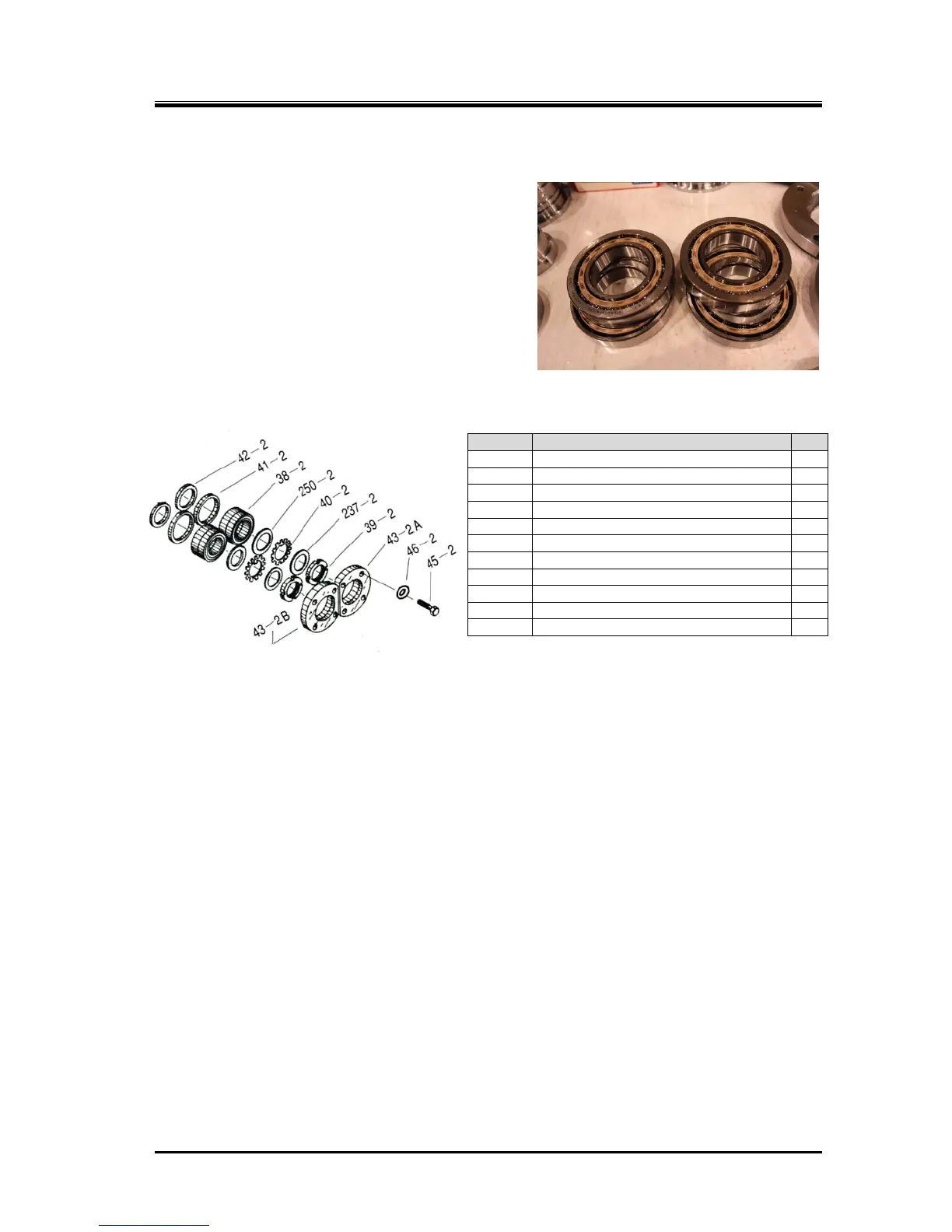
5.4.13 Thrust Bearing Block
Thrust bearing (picture to the right) is a face-to-face
angular contact ball bearing. This bearing only
receives thrust load and does not receive the radial
load perpendicular to the shaft because there is a gap
between the outer ring of the thrust bearing and the
bearing head. Apart from receiving the thrust load, the
bearing has the important role of securing the position
of the gap between the rotor and the discharge side of
the bearing head. This gap (end clearance) is
significantly linked with performance.
5.4.13.1 Disassembly of High-stage Thrust Bearing Block
Figure 5-10 High-stage Thrust Bearing Block
a) Remove the lock nut [39-2] that has been loosened. Then, remove the torsional slip washer [237-2],
lock washer [40-2], and thrust washer [250-2].
b) The clearance fit is applied to two gaps between the outer race of the thrust bearing and the bearing
head, between the inner race of the thrust bearing and the rotor shaft
Prepare a 1 or 2 mm diameter aluminum wire, make the tip of the wire flat by hammering, and
slightly bend the tip to make a hook. Then, insert the tip of the wire between the outer race and the
ball retainer of the thrust bearing [38-2] to hook and pull out the bearing. In this way, the bearing can
be easily removed.
c) The whole thrust bearing will be removed helped by the surface tension of the oil on the side face.
If you have failed to remove the whole bearing at once, put the components in the order of the
removal.
d) Attached to the inside of the thrust bearing are; thrust bearing outer race spacer [41-2] for the
bearing head-side outer ring, and the thrust bearing alignment spacer [42-2] for the rotor shaft side
inner race. To identify where to set, the thrust bearing outer race spacers and thrust bearing
alignment spacers have a stamped mark of "M" or "F" which means "for M rotor" or "for F rotor".
The bearing glands, thrust washers, thrust bearings, thrust bearing outer race spacers and thrust
bearing alignment spacers, which have been removed, should be divided into two groups (M rotor
group and F rotor group).
You must be very careful because if an assembly error is made to result in a wrong combination of
parts after failing to neatly arranging and separating the parts, it can lead to performance
degradation and/or dragging accident due to overheating caused by being too narrow end
clearance, for example.
P/N Part Name Qty
38-2 Thrust bearing (2) 2
39-2 Lock nut (2) 2
40-2 Lock washer (2) 2
41-2 Thrust bearing outer race spacer (2) 2
42-2 Thrust bearing alignment spacer (2) 2
43-2A Thrust bearing gland (2) A for F rotor 1
43-2B Thrust bearing gland (2) B for M rotor 1
45-2 Hexagon head screw (M8 x 30) 8
46-2 Spring washer (for M8) 8
237-2 Torsional slip washer (for 125***) 2
250-2 Thrust washer (for 125***) 2
 Loading...
