2202L5JE-DA-C5-N_2015.05.
3 Installation
Compound 2stage Screw Compressor 3.2 Installation Works
1612LSC Speed Increaser Type
3-4
3.2.4 Preparation for Installation
Installation Space
Prepare sufficient working space for easy operation, cleaning, maintenance, and inspection.
Illumination
Prepare lighting for easy operation, cleaning, maintenance, and inspection.
Ventilation
If natural ventilation is insufficient, install ventilation fans according to the regulations.
Piping
Table 3-1 Connected Piping List (Compressor)
Item Dimensions Remarks
Suction gas inlet MYCOM 125A (5″) See figure 3-2.
Low-stage gas outlet MYCOM 80A (3″) See figure 3-2.
High-stage gas inlet MYCOM 80A (3″) See figure 3-2.
High-stage discharge gas outlet MYCOM 65A (2½″) See figure 3-2.
Low-stage bearing (journal) oil inlet Rc1/2
Low-stage capacity control oil inlet (increase side) Rc1/4
Low-stage capacity control oil inlet (decrease side) Rc3/8
Oil injection inlet Rc3/8
Mechanical seal and speed increaser gear oil inlet Rc1/4
High-stage bearing (journal) oil inlet Rc3/8
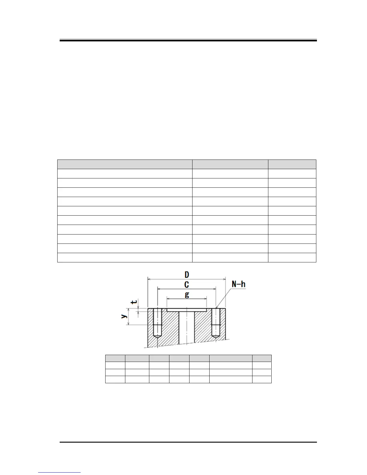
D t g C N-h y
65A □144 4.5 101 144 4-M16 × P2 24
80A □154 4.5 119 158 4-M20 × P2.5 25
125A 270 5 174 230 8-M20 × P2.5 27
Figure 3-2 MYCOM Flange Dimensions
* In external dimensions figures 2-1 in “2.2.2 Outer
Dimensions” in chapter 2 of this manual, these
MYCOM flange dimensions are noted as MYK**A.
 Loading...
