2202L5JE-DA-C5-N_2015.05.
5 Maintenance and Inspection
Compound 2-stage Screw Compressor 5.5 Reassembly
1612LSC Speed Increaser Type
5-47
5.5.4 Rotor Assembly
Note on the rotor profile of 1612**C
The rotor profile design was changed from A Profile to O Profile in July 1994.
The biggest difference is the lobe tip edges. Profile A has the lobe tip edges while profile O does not
have them
Make sufficient adjustments to the rotor. Smooth over all damage on the shaft surface of the bearing
and seal using fine sandpaper.
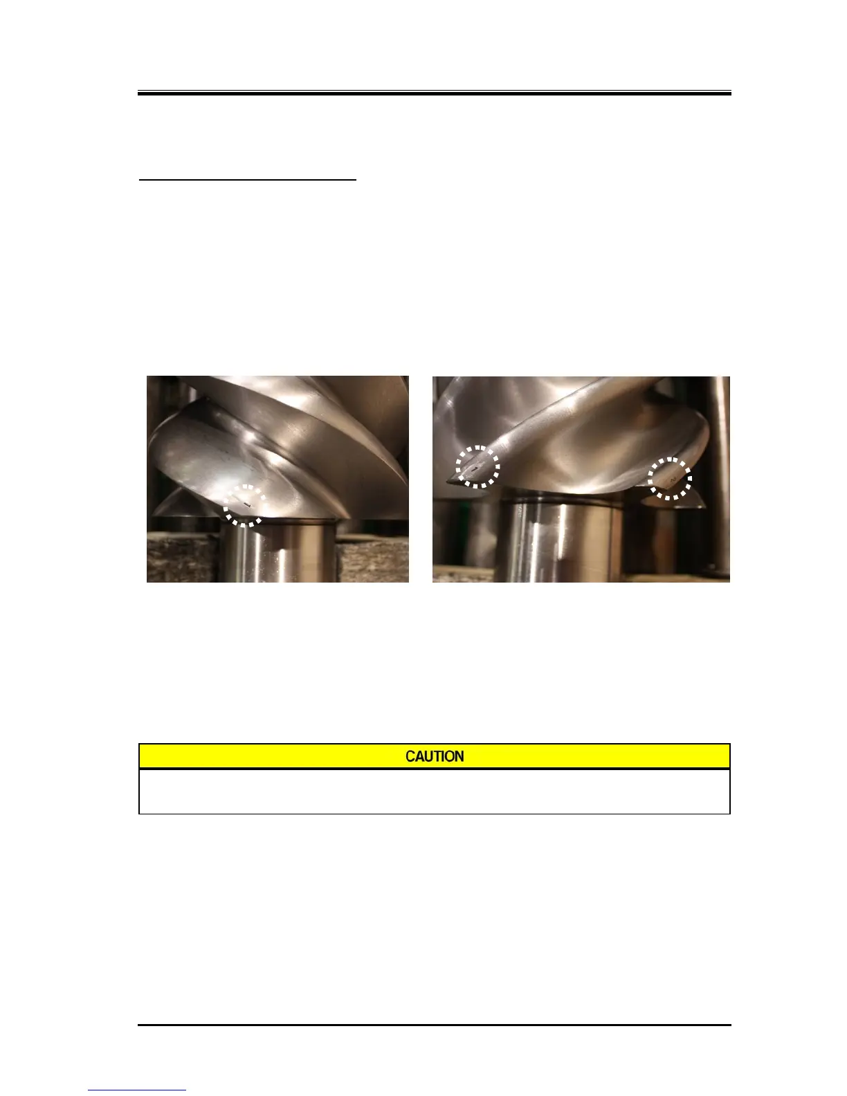
Both the M and F rotors have unique messing positions which are indicated by engravings.
When attaching to the main rotor casing, it is possible to align their positions easily by checking the
engraved numbers for the M rotor on the peak of the lobe on the discharge side and the F rotor on the
peak of the lobe on the suction side.
M Rotor Assembly Mark F Rotor Assembly Mark
a) Lubricate the main bearings in the bearing head and the rotor shaft bearings sufficiently.
b) While it is easier to mate the markings if the F rotor is first installed into the casing, it is not a mistake
to install the M rotor first.
c) Regardless of which rotor is installed first, engage the M rotor lobe, which has engraved mark 1,
between the F rotor lobes having engraved marks 1 and 2. As factors, such as mating of lobes,
balance, etc., should be considered, be sure to mate the lobe profiles as instructed.
Since the outer side of the rotor touches the rotor casing in this state, do not rotate
too much. Rotating may cause the rotor teeth to wear.
 Loading...
