2202L5JE-DA-C5-N_2015.05.
5 Maintenance and Inspection
Compound 2-stage Screw Compressor 5.4 Disassembly and Inspection
1612LSC Speed Increaser Type
5-40
5.4.17 Low-stage Bearing Head and Main Bearings
Apart from when disassembling and inspecting the unloader slide valve, it is not necessary to separate
the low-stage bearing head [11-1] and the main rotor casing [1-1].
However, according to the design modification in July 1986, of the low-stage bearing head the part
where the unloader push rod is set has been changed.
Compressors manufactured before this modification need to be separated into low-stage bearing head
and main rotor casing to replace O-ring [197] attached to this part.
After this modification, since the O-ring gland [326] has been added, the O-ring [197] replacement work
is able to easily by removing the O-ring gland.
5.4.17.1 Disassembly
a) Remove all of the hexagon socket head cap screws [2-1].
b) Drive alignment pins [3-1] into the main
rotor casing flange side.
c) Separate the bearing head and main rotor
casing using two jacking threaded holes in
the bearing head flange part.
d) Separate the embedded unloader push
rod [67] parallel to the axis.
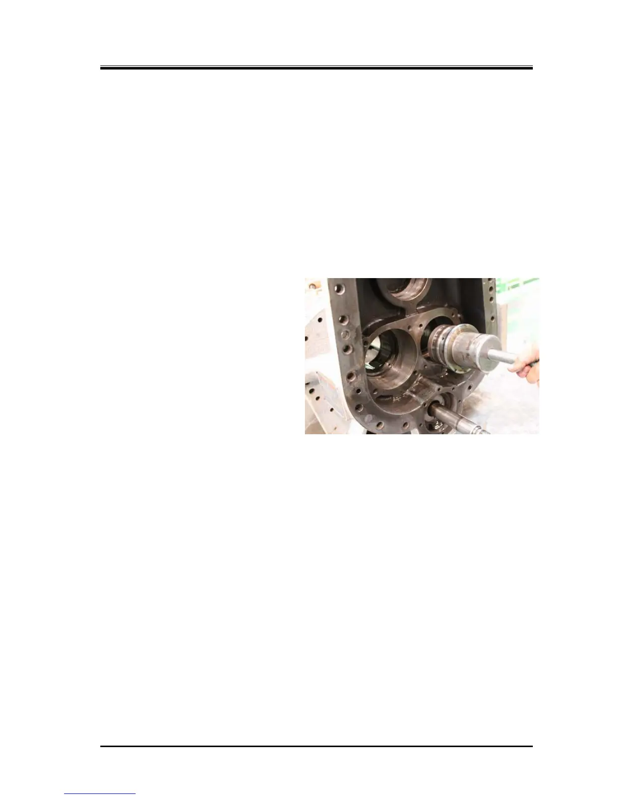
e) Remove the internal snap ring [29-1] and
then remove the main bearing and then
pushing it from the main rotor casing side
via a pad. Otherwise, use a special tool to
pull it out as shown in the right picture.
5.4.17.2 Inspection
a) Low-stage bearing head has two lubrication holes for the speed increaser gear and the speed
increaser gear spindle. These lubrication holes are screwed in the oil flow control throttles [196-2],
check that there are not clogged in the lubrication holes and throttles.
b)
Other parts check in the same way as the high-stage.
 Loading...
