ND-45383 (E) CHAPTER 3
Page 99
Revision CD 1.0
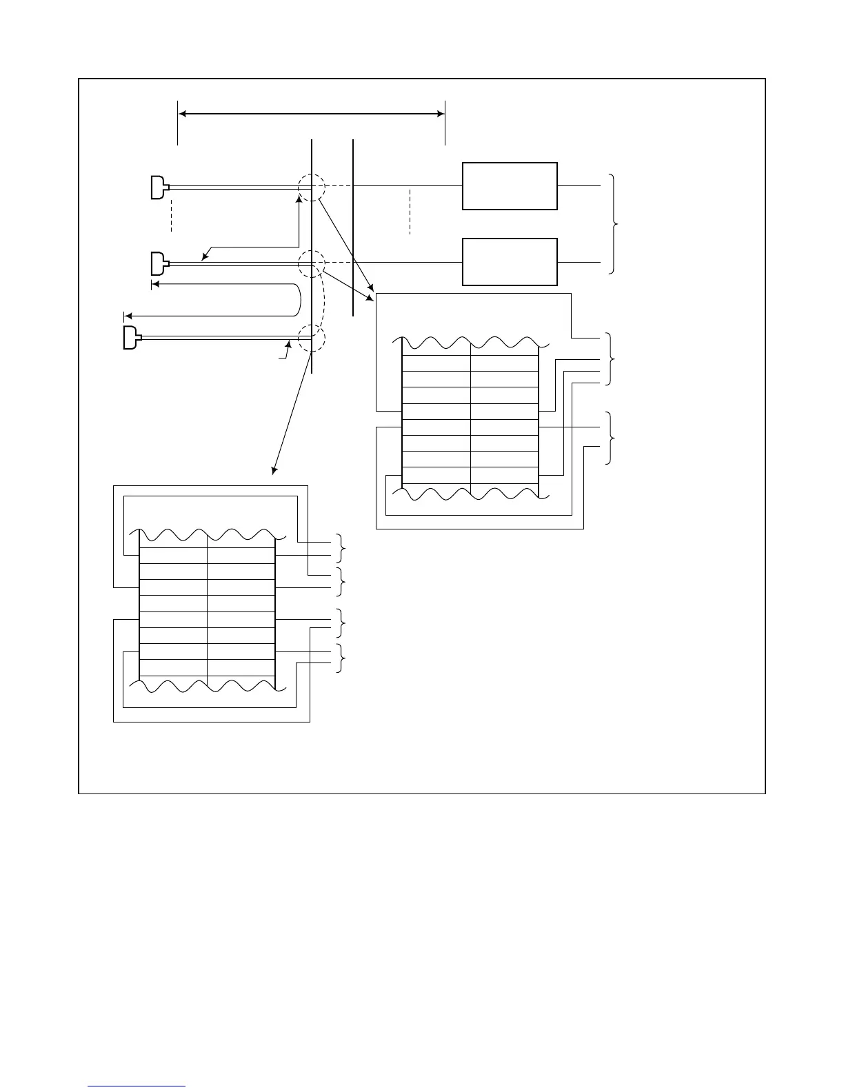
Figure 3-24 Connection of Digital Interface for IMG (ICS)
LT
LT3 (PIMA0/B0)
MDF
PCM CABLE (2P)
PCM Carrier
Equipment
LT
PCM CABLE (2P)
PCM Carrier
Equipment
"LT" Connector Cable
(25P)
MAXIMUM 100 meters
(328 feet)
Note
"LT3" Connector Cable
(25P)
To DRU-23-S3
MAXIMUM 200 meters (656 feet)
E
RB
POUTB
TB
E
RA
POUTA
TA
DLI LEADS
To PCM Carrier
Equipment
To "DIU x A&B" leads
of PLO card
(to be connected only
for sync. clock
distribution route).
DIU3B DIU3A
PLO LEADS
To "POUTA&B leads of the DLI card in the 1st clock distribution route.
DIU1B DIU1A
DIU2B DIU2A
DIU4B DIU4A
To "POUTA&B leads of the DLI card in the 2nd clock distribution route.
To "POUTA&B leads of the DLI card in the 3rd clock distribution route.
To "POUTA&B leads of the DLI card in the 4th clock distribution route.
Note: If dual PLO are provided, the “LT7” connector cable of PIMA0 or “LT5” connector cable of PIMB0
is also cross connected with the DLI card of the clock distribution route.
 Loading...