ND-45383 (E) CHAPTER 5
Page 117
Revision CD 1.0
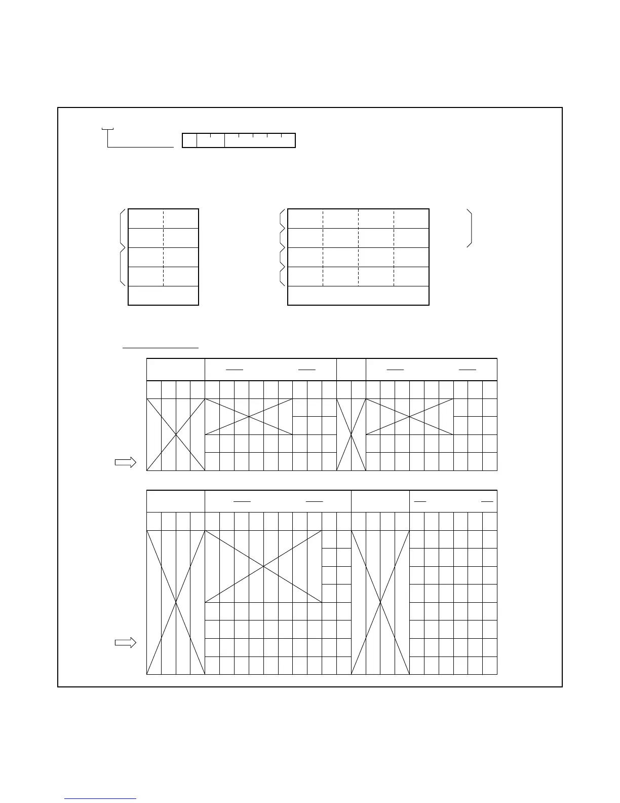
2.1.1 Circuit Card Location Information
The accommodated location information of each circuit card is given by a hexadecimal number.
Figure 5-1 Relation between Accommodated Location Information and Mounting Location
U=2
U=0
U=2
U=0
U=3
U=1
U=3
U=1
LCMA/LCMC
MG=00
MG=01
PIMA3
PIMA2
PIMA1
PIMA0
• When PIMA is mounted
U=0
U=0
U=0
U=0
U=1
U=1
U=1
U=1
U=2
U=2
U=2
U=2
U=3
U=3
U=3
U=3
LCMA/LCMC
• When PIMB is mounted
PIMB3
PIMB2
PIMB1
PIMB0
for MMG (ICS)
MG=01
MG=00
MG=01
MG=00
00 01 02 03 04 05 06 07 08 09 10 11 12 13 14 15 16 17 18 19 20 21 22 23
15 19 23 15 19 23
14 18 22 14 18 22
01 03 05 07 09 11 13 17 21 01 03 05 07 09 11 13 17 21
00 02 04 06 08 10 12 16 20 00 02 04 06 08 10 12 16 20
00 01 02 03 04 05 06 07 08 09 10 11 12 13 14 15 16 17 18 19 20 21 22 23
15 23 07 15 23 07 15 23
14 22 06 14 22 06 14 22
13 21 05 13 21 05 13 21
12 20 04 12 20 04 12 20
03 07 11 15 19 23 03 07 11 19 03 11 19 03 11 19
02 06 10 14 18 22 02 06 10 18 02 10 18 02 10 18
01 05 09 13 17 21 01 05 09 17 01 09 17 01 09 17
00 04 08 12 16 20 00 04 08 16 00 08 16 00 08 16
LINE/TRUNK LINE/TRUNK
LINE/TRUNK LINE/TRUNK
PIMA
G : Group Number
SLOT No.
GROUP No.
PIMB
SLOT No.
GROUP No.
MG U G
1 : XX00 00
MG:
U:
G:
Module Group Number
Unit Number
Group Number
 Loading...