Nikon N Series/K Series Total Station Instruction Manual 147
Checking and Adjustment 6
4. If the image is not in the same
position, adjust the optical
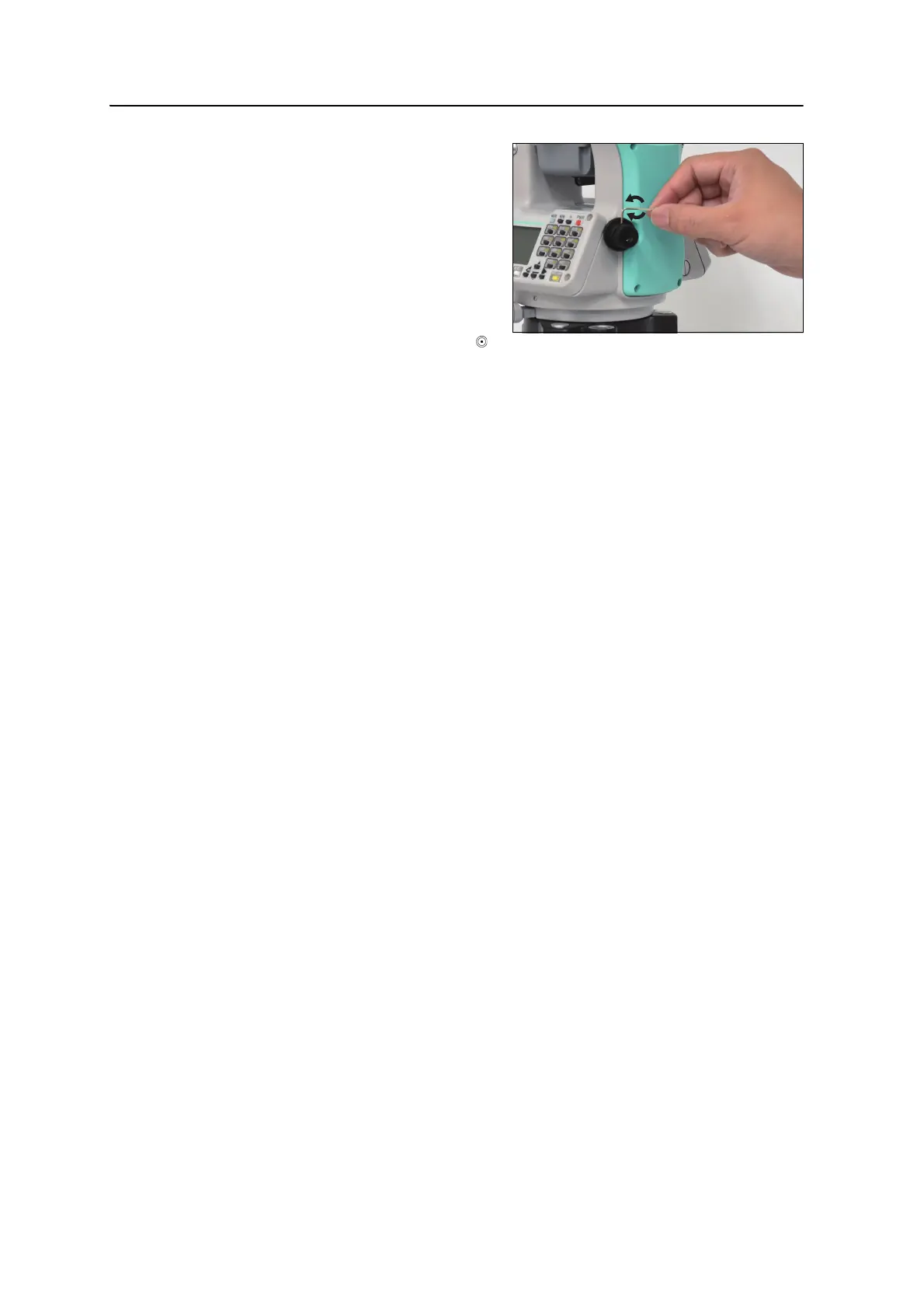
plummet:
a. Use the supplied hexagonal
wrench to turn the adjustment
screws until the image of the
X is in Position P. Position P
is the center point of the line
connecting the X and the
center of the reticle mark .
b. Repeat from Step 2.
Zero Point Errors of Vertical Scale and Horizontal Angle Corrections
Checking
1. Set up the instrument on the tripod.
2. Follow the leveling procedures described in Leveling, page 15.
3. Flip the telescope to the Face-1 position.
4. Sight a target that is within 45° of the horizontal plane.
5. Read the vertical angle from the VA1 field in the Basic Measurement Screen
(BMS).
6. Rotate the instrument 180° and flip the telescope to the Face-2 position.
7. Read the vertical angle from the VA2 field.
8. Add the two vertical angles together, VA1 + VA2.
– No adjustment is required if the zero reference for vertical angles (VA
zero setting) is set to Zenith, and VA1 + VA2 equals 360°.
– No adjustment is required if the zero reference for vertical angles (VA
zero setting) is set to Horizon, and VA1 + VA2 is either 180° or 540°.
– An adjustment is required if VA1 + VA2 is not one of the values listed
above.
Note – The difference between the vertical angle reading the relevant angle (either
360° for Zenith, or 180° or 540° for Horizon) is called the altitude constant.
 Loading...