Programming 15088:K 3/21/01
3-11
Section 1.1.1 LIB Installation
D
}X1X1X
1=INST
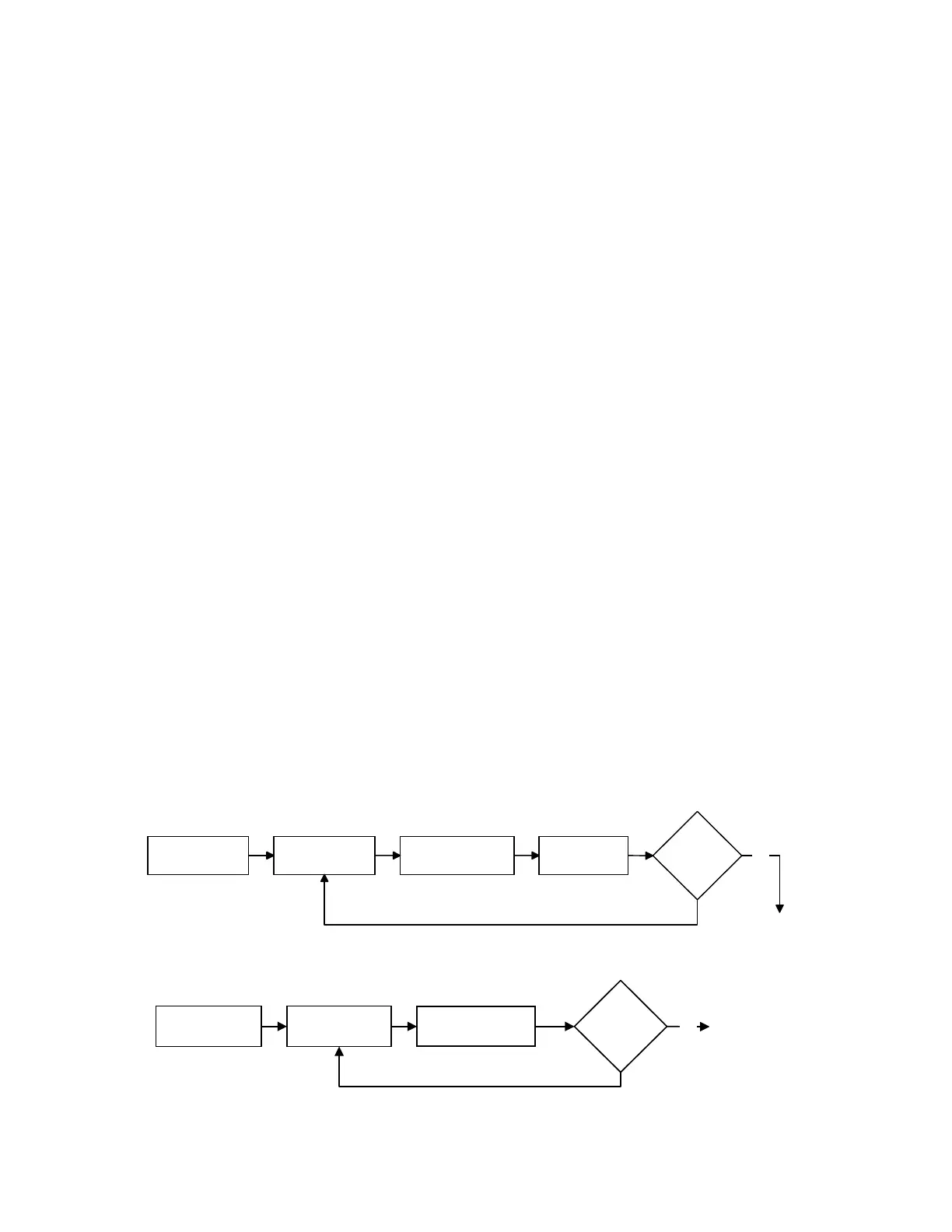
Option 1 from the Partial System Programming submenu allows the installation or removal of LIB SLC Loops
from memory. The LIB boards must still be physically installed or removed from the system to prevent a
system trouble condition. The Installation Option flow chart is located in Figure 1-3.
The AM2020 is capable of a maximum of ten LIB Signaling Line Circuits (1980 devices total in the system).
The AFP1010 is capable of a maximum of four LIB Signaling Line Circuits (792 devices total in the system).
The following programming example illustrates the installation of Loop Interface Board number 3.
PRESS@1=INST,2=STY,3=TDLY,4=AVPS,5=ZBND,6=EXTEQ,7=LOCP,8=ISIB,9=PARM@@@@@@@@@:@1
ENTER@THE@LIB@BOARD@NUMBER@TO@CHANGE@(1@-@10)@@@@@@@@@@@@@@@@@@@@@@@@@@@@@@@:@3
IS@LIB@BOARD@03@TO@BE@INSTALLED@IN@SYSTEM?@(Y=YES,N=NO)@@@@@@@@@@@@@@@@@@@@@@:@Y
ENTER@THE@STYLE@OF@SLC@LOOP@03@(6@OR@4)@@@@@@@@@@@@@@@@@@@@@@@@@@@@@@@@@@@@@@:@6
DO@YOU@WANT@TO@CHANGE@ANOTHER@LIB@BOARD?@(Y=YES,N=NO)@@@@@@@@@@@@@@@@@@@@@@:@N
PROGRAMMING@COMPLETE@@-@@POWER@DOWN@TO@MAKE@APPROPRIATE@CHANGES
Section 1.1.2 LIB SLC Loop Style D }X1X2X
2=STY
Option 2 from the Partial System Programming submenu allows the programmer to change in AM2020/
AFP1010 memory the NFPA style for the Signaling Line Circuit (SLC) connected to each LIB. The SLC must still
be field wired in accordance with the style set in memory (Chapter One-Installation). The Style Option flow chart
is located in Figure 1-4.
The following programming example illustrates setting SLC Loop number 5 as an NFPA Style 6 circuit. The
CRT screen prompts are displayed in the priority that they appear (top to bottom).
PRESS@1=INST,2=STY,3=TDLY,4=AVPS,5=ZBND,6=EXTEQ,7=LOCP,8=ISIB,9=PARM@@@@@@@@@:@2
ENTER@THE@SLC@LOOP@NUMBER@TO@CHANGE@(1@-@10)@@@@@@@@@@@@@@@@@@@@@@@@@@@@@@@@:@5
ENTER@THE@STYLE@OF@SLC@LOOP@05@(6@OR@4)@@@@@@@@@@@@@@@@@@@@@@@@@@@@@@@@@@@@@@:@6
DO@YOU@WANT@TO@CHANGE@ANOTHER@SLC@LOOP?@(Y=YES,N=N0)@@@@@@@@@@@@@@@@@@@@@@@@@:@N
Figure 1-4 Style Option Flow Chart
Refer to Chapter One of this manual for information on LIB-400 and its correct slot address. See notes in Section
1.1, Partial System Programming.
Figure 1-3 Install Option Flow Chart
1 = INST
Enter LIB
board # (1-10)
Enter Style
of SLC Loop
Install/Remove
LIB selected
Change
another
LIB?
Yes
(Exit Prog Mode)
No
(Exit Prog Mode)
2 = STY
Enter Loop #
Enter NFPA Style
for loop (6 or 4)
Change
Another
Style?
Yes
No
 Loading...


