Gigabit Ethernet
PRELIMINARY INFORMATION
Jetson Orin NX Series and Jetson Orin Nano Series DG-10931-001_v1.1 | 44
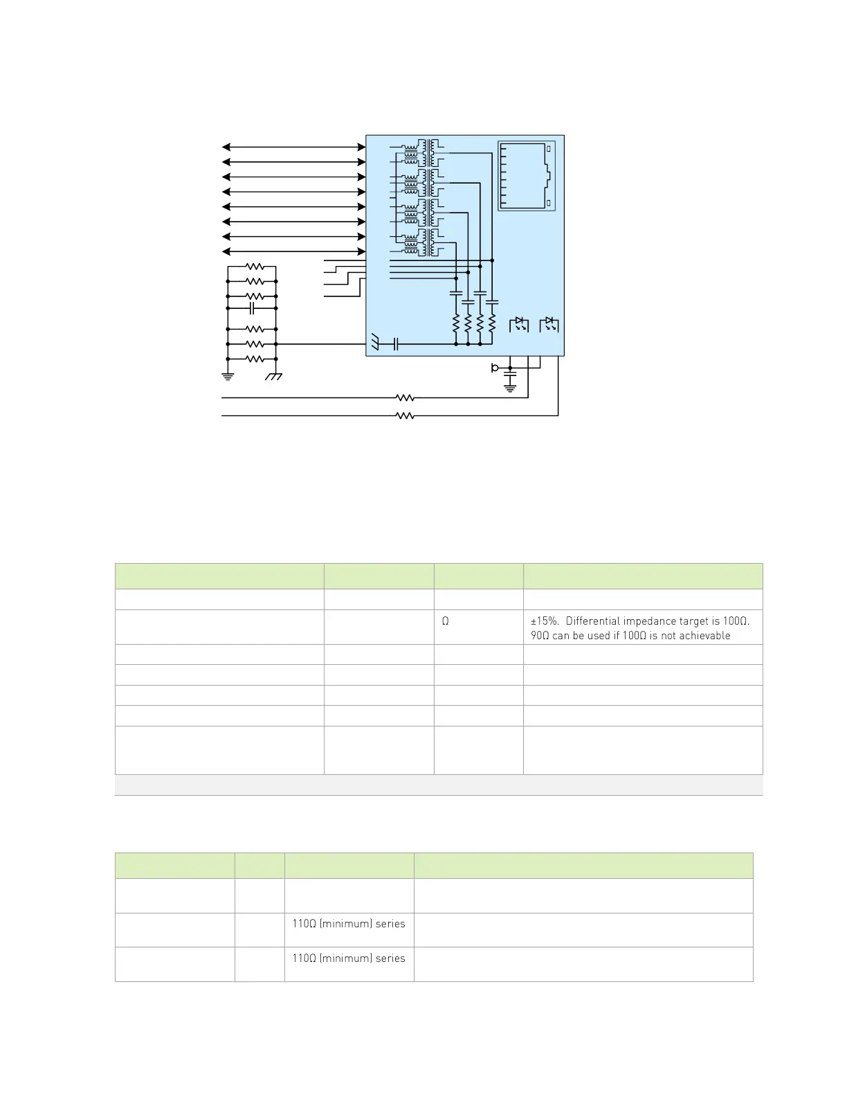
Figure 8-2. Gigabit Ethernet Magnetics and RJ45 Connections
(J8) TXD3-
(J7) TXD3+
(J6) TXD1-
(J5) TXD2-
(J4) TXD2+
(J3) TXD1+
(J2) TXD0-
(J1) TXD0+
22nF
each
each
J1
J2
J3
J6
J4
J5
J7
J8
MD0+
MD0-
MD1+
MD1-
MD2+
MD2-
MD3+
MD3-
MCT
GRN+
GRN
YEL+
YEL
VC1
VC2
VC3
VC4
0.1uF
GBE_MDI0_P
GBE_MDI0_N
GBE_MDI1_P
GBE_MDI1_N
GBE_MDI2_P
GBE_MDI2_N
GBE_MDI3_P
GBE_MDI3_N
110
110
GBE_LED_LINK
GBE_LED_ACT
1000pF
VDD_3V3_SYS
100pF
0.05
0.05
0.05
0.05
0.05
0.05
Place resistors &
capacitor around
chassis GND shape
POE_VC1
POE_VC2
POE_VC3
POE_VC4
8.1.1 Ethernet MDI Routing Guidelines
The following tables describes the ethernet signal routing requirements and connections.
Table 8-2. Ethernet MDI Interface Signal Routing Requirements
Trace impedance (Diff pair / Single
Ended)
Min trace spacing (pair-pair)
Max within pair (intra-pair) skew
Max pair to pair (inter-pair skew)
Ideally there should be no vias, but if required
for breakout to Ethernet controller or
magnetics, keep very close to either device.
Notes: NVIDIA Orin does not support delay or skewing of clock vs. data. This must be enabled in the PHY.
Table 8-3. Ethernet Signal Connections
Gigabit Ethernet MDI IF Pairs: Connect to Magnetics -/+ pins
Gigabit Ethernet Link LED: Connect to green LED cathode on RJ45
connector. Anode connected to VDD_3V3_SYS
Gigabit Ethernet Activity LED: Connect to yellow LED cathode on
RJ45 connector. Anode connected to VDD_3V3_SYS
 Loading...


