Audio
PRELIMINARY INFORMATION
Jetson Orin NX Series and Jetson Orin Nano Series DG-10931-001_v1.1 | 65
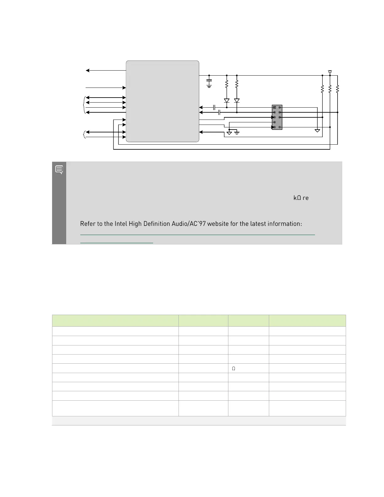
Figure 11-1. Audio Connection Example
Audio Codec
IRQ
MCLK
BCLK
LRCLK
SDIN
SDOUT
HP_JACK_DETECT
PRESENCE#
SDA
SCL
MICBIAS
MICROPHONE_IN_L
MICROPHONE_IN_R
HEADPHONE_OUT_R
HEADPHONE_OUT_L
MIC_IN_DETECT
I2Sx_FS
I2Sx_DOUT
I2Sx_DIN
I2Sx_SCLK
Jetson Module
I2S0 or I2S1
1uF
Avail. Jetson
Module GPIO
(see note 1)
2.2uF
1uF
Jetson Module
GPIO09
(AUD_MCLK)
Jetson Module
I2C (see note 2)
I2C2_SDA
I2C2_SCL
Audio Panel
Header
1
3
5
7
9
2
4
6
8
10
VDD_1V8
10k
2.2k
2.2k
1M
1M
PORT_1L
PORT_1R
PORT_2R
SENSE_SEND
PORT_2L
GND
PRESENCE#
SENSE1_RETURN
Key
SENSE2_RETURN
Notes:
1. The Interrupt pin from the audio codec can connect to any available Orin module GPIO. If the
pin must be wake-capable, choose one of the GPIOs that supports this function.
2. I2C2 supports 1.8V operation since the interface is pulled to 1.8V through 2.2 sistors on
the module. If another I2C interface on Orin module is used, a level shifter will be required as
all the others are 3.3V.
3.
https://www.intel.com/content/www/us/en/support/articles/000005512/boards-and-
kits/desktop-boards.html.
11.1.1 I2S Routing Guidelines
This section describes the I2S routing guidelines.
Table 11-2. I2S Interface Signal Routing Requirements
Configuration and device organization
Breakout region impedance
Via proximity (signal to reference)
Trace spacing Microstrip or Stripline
Max trace length/delay skew between SCLK and
SDATA_OUT/IN
Note: Up to four signal vias can share a single GND return via.
 Loading...


