Miscellaneous Interfaces
PRELIMINARY INFORMATION
Jetson Orin NX Series and Jetson Orin Nano Series DG-10931-001_v1.1 | 68
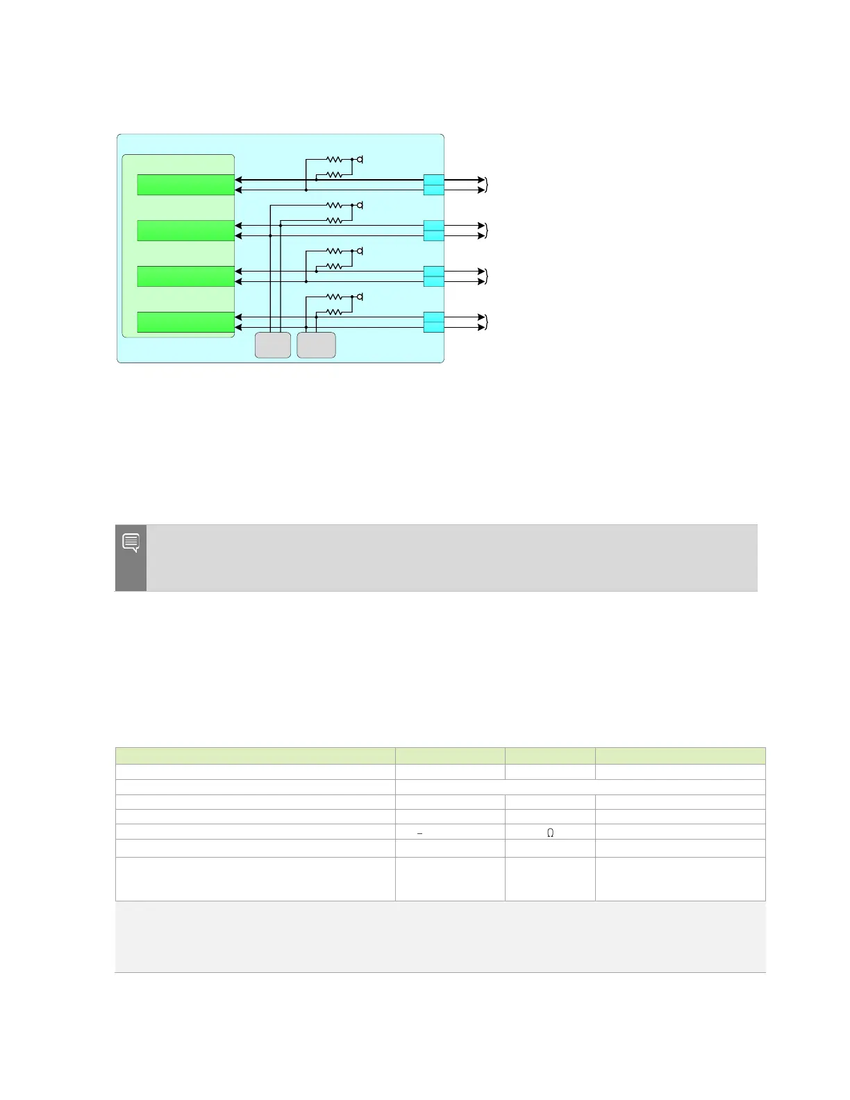
Figure 12-1. I2C Connections
Jetson
SoC I2C
GP54_I2C3_CLK
GP55_I2C3_DAT
GP126_I2C1_CLK
GP127_I2C1_DAT
GP13_I2C2_CLK
GP14_I2C2_DAT
VDD_3V3_SYS
2.2k
VDD_1V8
VDD_3V3_SYS
Used as camera module control interface
or available for misc. 3.3V I2C devices.
CAM_I2C_SCL
CAM_I2C_SDA
I2C2_SCL
I2C2_SDA
I2C1_SCL
I2C1_SDA
I2C0_SCL
I2C0_SDA
Available for misc. 1.8V I2C devices
Available for misc. 3.3V I2C devices
215
213
232
234
185
187
GP15_I2C8_CLK
GP16_I2C8_DAT
VDD_3V3_SYS
Available for misc. 3.3V I2C devices
189
191
2.2k
2.2k
2.2k
2.2k
2.2k
1.5k
1.5k
Power
Monitor
7'h40
ID
EEPROM
7'h50
12.1.1 I2C Design Guidelines
Care must be taken to ensure I2C peripherals on the same I2C bus connected to the Orin
module, do not have duplicate addresses. Addresses can be in two forms: 7-bit, with the
read/write bit removed or 8-bit including the read/write bit. Be sure to compare I2C device
addresses using the same form (all 7-bit or all 8-bit format).
Note: The Orin module I2C interfaces have pull-ups on the module (See Table 12-1 or Table 12-3
for values). Pads for additional pull-ups are recommended in case a stronger pull-up is required
due to additional loading on the interfaces.
12.1.2 I2C routing Guidelines
This section describes the I2C routing guidelines for Orin module.
Table 12-2. I2C Interface Signal Routing Requirements
Max frequency: Standard-mode / Fm / Fm+
Single ended, bi-directional, multiple initiators/targets
Max loading: Standard-mode / Fm / Fm+
Max trace length/delay
Standard Mode
Fm, Fm+ Modes
Notes:
1. Fm = Fast-mode, Fm+ = Fast-mode Plus
2. Avoid routing I2C signals near noisy traces, supplies or components such as a switching power regulator.
3. No requirement for decoupling caps for PWR reference.
 Loading...


