BA_OTE 3+4_Endkunde_EN_V03_20170726.docx Page 10 of 52
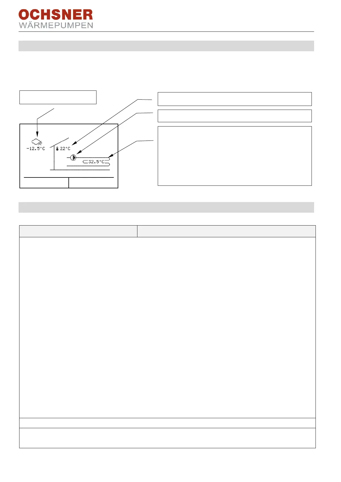
5.4 Temperature image
The temperature image gives an overview of the condition and temperatures of direct
heating circuits and mixing circuits.
5.5 Operational data
02-051 Status heating circuit
(e.g. heating limit exceeded)
1 = normal heating mode
Heating operation (reduced set value)
4 = frost protection mode
Control to "frost protection temperature" to avoid the heat-
ing circuit freezing up.
(Heating circuit OFF during de-icing)
7 = holiday mode
8 = party mode
9 = normal cooling mode
11 = economy cooling mode
Cooling operation (reduced set value)
13 = manual operation
15 = party mode cooling
16 = drying: heating phase
(floor screed heating programme active)
17 = drying: steady phase
(floor screed heating programme active)
18 = drying: cooling phase
(floor screed heating programme active)
(floor screed heating programme still active)
(cooling to external set value input)
(heating to external set value input)
00-000 Outdoor temperature
Current outside temperature
02-020 Outdoor temperature av-
erage value
Mean outside temperature (relevant for heat-
ing/cooling limit)
Room temperature (TI) (only if there is a room unit)
Flow temperature
Depending on the type of system, the measured val-
ue will be taken from one of the following sensors:
- Buffer tank in system (TPO)
- no buffer (direct heating circuit (TWV))
- mixed heating circuit (TMK)
Heating circuit pump (HKP) ON-OFF
 Loading...