BA_OTE 3+4_Endkunde_EN_V03_20170726.docx Page 6 of 52
4 System operation
The heat pump operation takes place by
means of the basic operating panel. This
is easily accessible in a plastic housing
mounted on the heat pump. The user has
2 buttons and an illuminated display at
his disposal.
The heat pump has no separate
main switch. In emergencies, the
system must be switched off by
means of the specified circuit
breakers. The circuit breakers
must be so reachable as to en-
sure a switching off at any time.
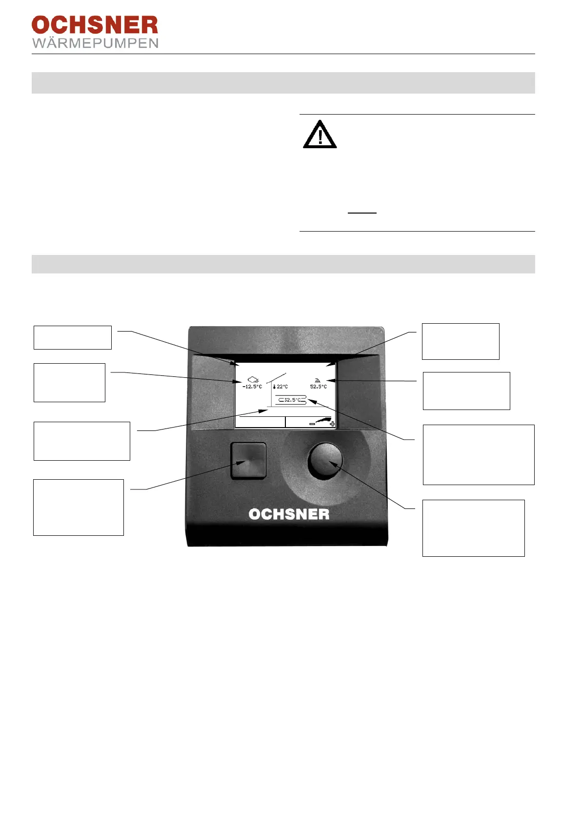
4.1 Main display
Current temperatures and operational conditions are shown in the main display.
Fig. 5: Control unit MB64xx
Control using the control unit MB64xx in the heat pump's inside unit is described as fol-
lows. Separate operating instructions are available for the room control units and the
room terminal.
Time of day
System flow tempera-
ture
(e.g.: buffer top)
Outside tem-
perature
Heat pump opera-
tional condition
Button B
one step back
(ESC)
Hot water tem-
perature
Button A
Menu selection and
confirmation
 Loading...