44015503TH Rev. 1
206 /
Oki Data CONFIDENTIAL
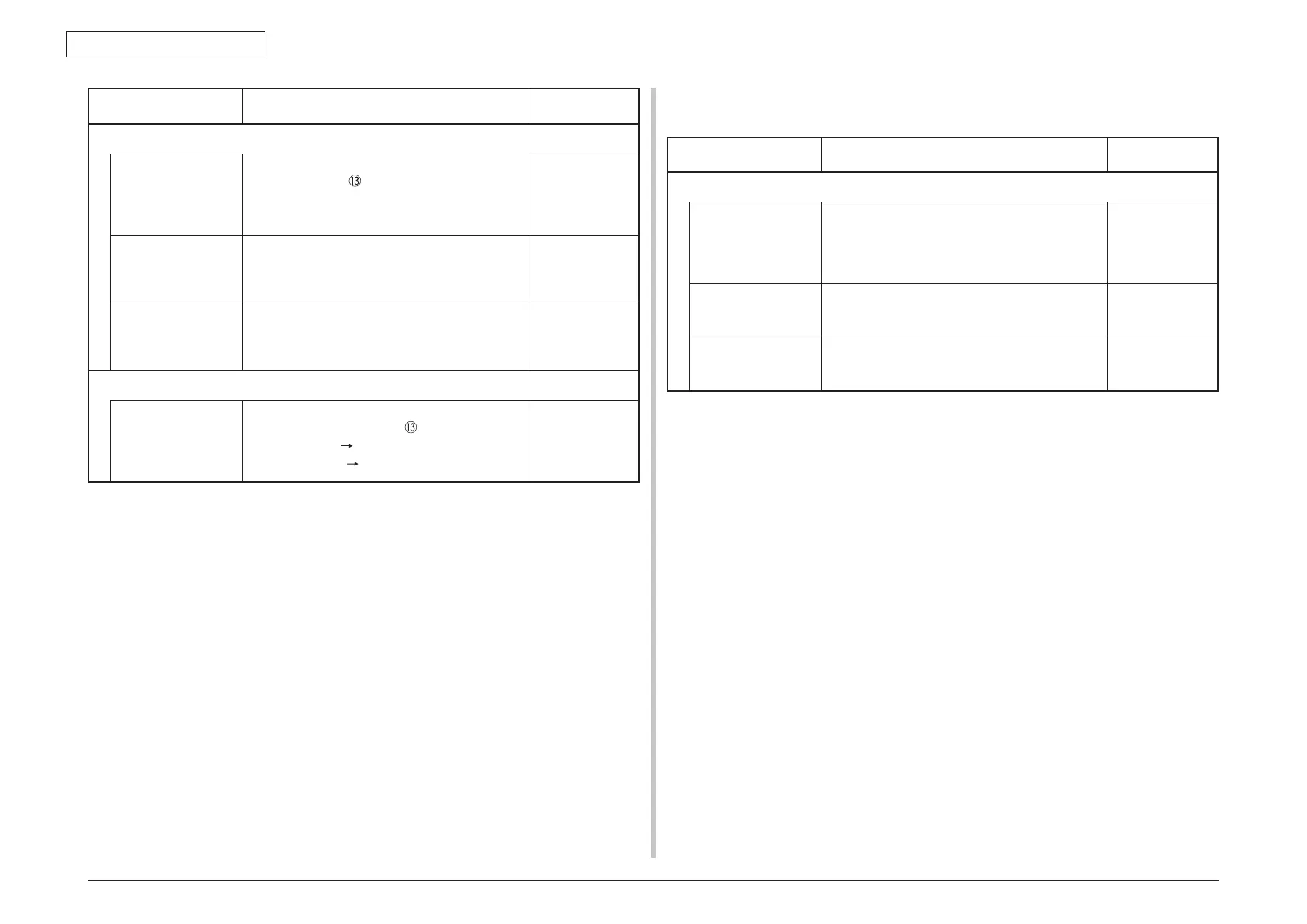
7. TROUBLESHOOTING PROCEDURE
Check item Check work
Action to be taken
at NG
(14-1-2) Check the system connection
Check the system
connection from
the PU board to the
option tray board
(
V7Y PCB).
Check that the cable between the PU board
option connector to the option tray board is
normally connected.
Correct the
connections.
Square connector
connecting the
option tray unit to
the printer.
Check if any foreign material exists in the
connecting portion of the square connector.
Remo
ve the
foreign material.
Square connector
connecting the
option tray unit to
the printer.
Is the terminals of the square connector
damaged?
Replace the
connector.
(14-2-3) Check the control signals.
Check the control
signal that is output
from the PU board
to the option tray
board (
V7Y PCB).
Check the control signal that is output from the
PU board option connector .
Pin-5: TXD (PU
2nd)
Pin-3: RXD (2nd
PU)
Replace the PU
board.
7.5.2.(15) LED head cannot be recognized. (error code 131, 132, 133, 134)
(15-1) Service call 131 to 134 (LED HEAD Missing)
Check item Check work
Action to be taken
at NG
(15-1-1) Check the system connection
Connecting
condition at the CU
board connector
and at the head
connector.
Check the connecting condition of the FFC by
the visual inspection.
Correct the
connection
to the normal
connecting
condition.
Head FF
C Remove the head FFC from the printer. Check
if any open-circuit or peeling-off of sheath has
occurred or not throughout the cable.
Replace the
head FFC or the
CU board.
Conduction of the
fuse on the CU
board.
Chec
k that 5V appears across the capacitors
CP7 and CP8. (Refer to section 7.6.)
Replace F504,
F506 or replace
the CU board.
 Loading...