44015503TH Rev. 1
81 /
Oki Data CONFIDENTIAL
4. REPLACEMENT OF PARTS
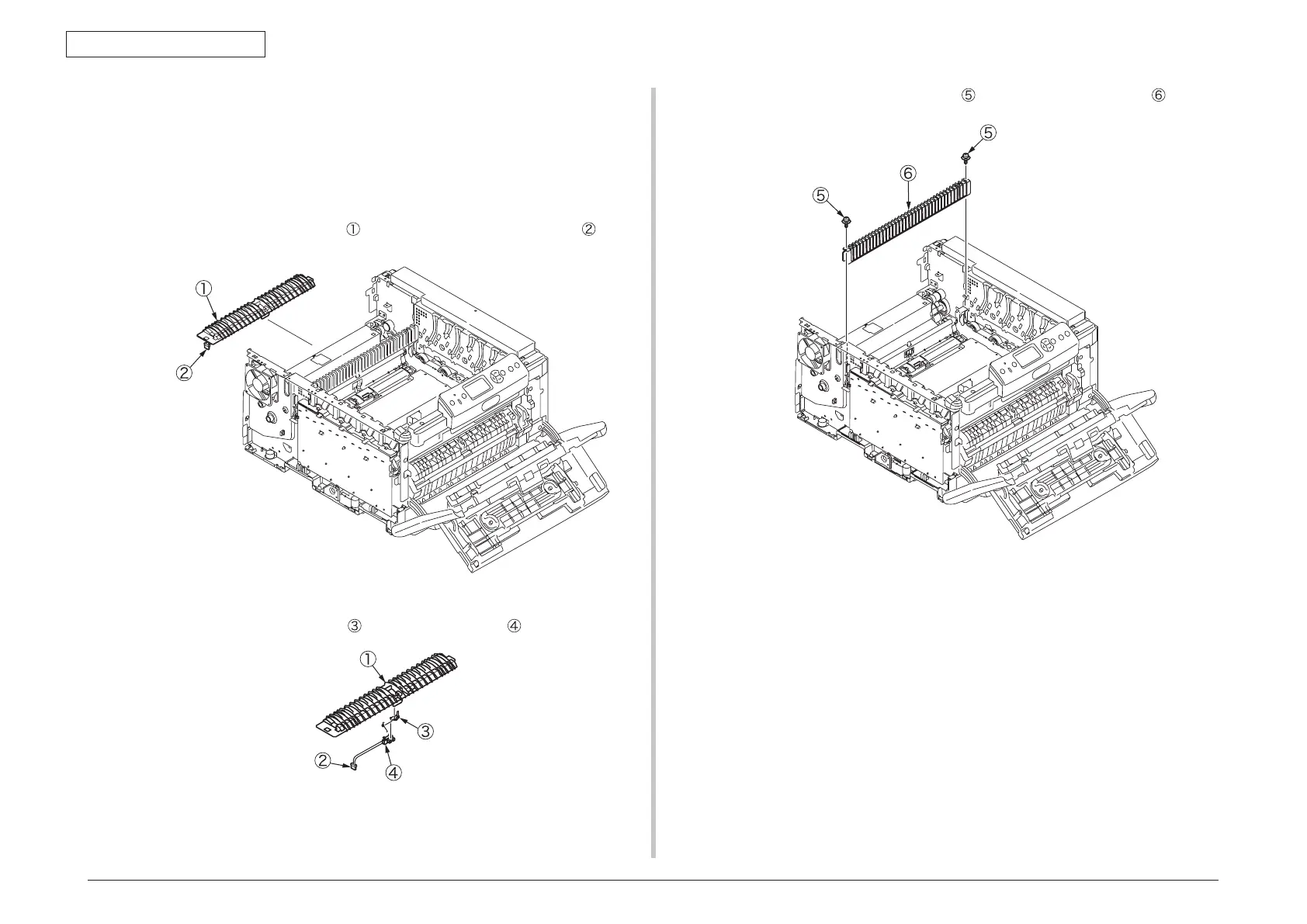
4.2.14 Guide-ejection Assy.-lower, color-registration
Assy. and relay board (P6Y)
(1) Remove the left side, right side and rear covers, the top cover Assy., the print
engine controller PCB and the guide-ejection Assy.-upper (see sections 4.2.3, 4.2.4,
4.2.5, 4.2.8, 4.2.9 and 4.2.13).
(2) Slide out the guide-ejection-lower
to the left and remove the connector .
(3) Remove the lever-ejection sensor
and the ejection sensor .
(4) Remove the two screws (silver-colored)
to remove the auxiliary Assy. .
 Loading...