Page: 37
Service Guide ML520/521
Chapter 2 Principles of Operation
2.1.07 Alarm Circuit
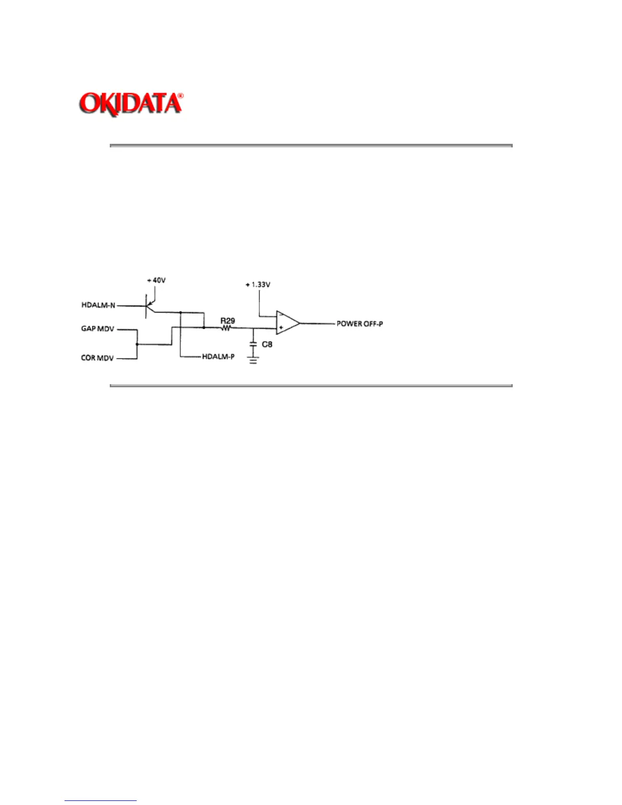
Driver Circuit Alarm Processing
The printhead driver output and the head gap magnet output drive signals are monitored at R29 and C8.
The POWER OFF-P signal is output by the comparator (Location 02C: IC2901) when driven for more than
the specified time. This signal becomes the ALM signal. The ALM signal is sent to the power supply board
and causes the DC voltages to be turned off.
Copyright 1997, Okidata, Division of OKI America, Inc. All rights reserved. See the OKIDATA Business
Partner Exchange (BPX) for any updates to this material. (http://bpx.okidata.com)
 Loading...