Page: 42
Service Guide ML520/521
Chapter 2 Principles of Operation
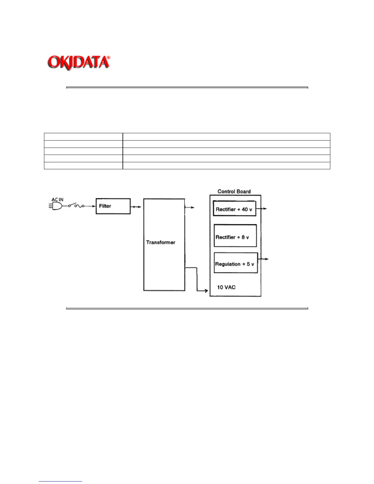
2.1.08 Power Supply Circuit
The switching type power supply circuit supplies the +5 vdc, +/-8 vdc, 10 VAC and +40 vdc.
Voltage/Signal
Purpose
+5 vdc IC logic levels, LED drive voltages
+8 vdc Serial interface line voltage, comparator IC
+10 VAC Serial interface line voltage and the printhead analog circuit
+40 vdc Printhead, space motor and line feed motor drive voltage
Copyright 1997, Okidata, Division of OKI America, Inc. All rights reserved. See the OKIDATA Business
Partner Exchange (BPX) for any updates to this material. (http://bpx.okidata.com)
 Loading...