9 Setting Up Slave Terminals
9 - 72
NX-series EtherNet/IP Coupler Unit User’s Manual (W536)
• One block of mapped output data and one block of mapped input data are maintained in the
EtherNet/IP Unit.
• Refer to 9-2-3 I/O Allocation Information on page 9-12 for details about I/O allocation and
EtherNet/IP Coupler Unit Status.
• Bit-sized NX Units (digital I/O types, up to 8 points), e.g. NX-ID3317, NX-OC2633 are
grouped together in words. They are mapped from the right-most bit to the left-most bit.
• Word-sized NX Units (analog I/O types) and 8 points or higher Bit-sized NX Units, e.g.
NX-AD2203, NX-DA203, NX-ID4342 (8 points Input), NX-OD5121 (16 points output) are
mapped in word units, from the low to the high word address.
• It is strongly recommended to add any NX Safety Units to the end of a configuration when
using the EtherNet/IP Coupler Unit without any stored Unit configuration information. If this
recommendation is not followed, the layout of EtherNet/IP Coupler Unit's I/O data blocks
will change when the configuration is downloaded. It that case, standard I/O data of the NX
Safety Units will be inserted in the EtherNet/IP Coupler Unit's I/O data blocks according to
their physical location in the configuration.
• The combined total size of mapped input data can be up to 512 bytes.
• The combined total size of mapped output data can be up to 512 bytes.
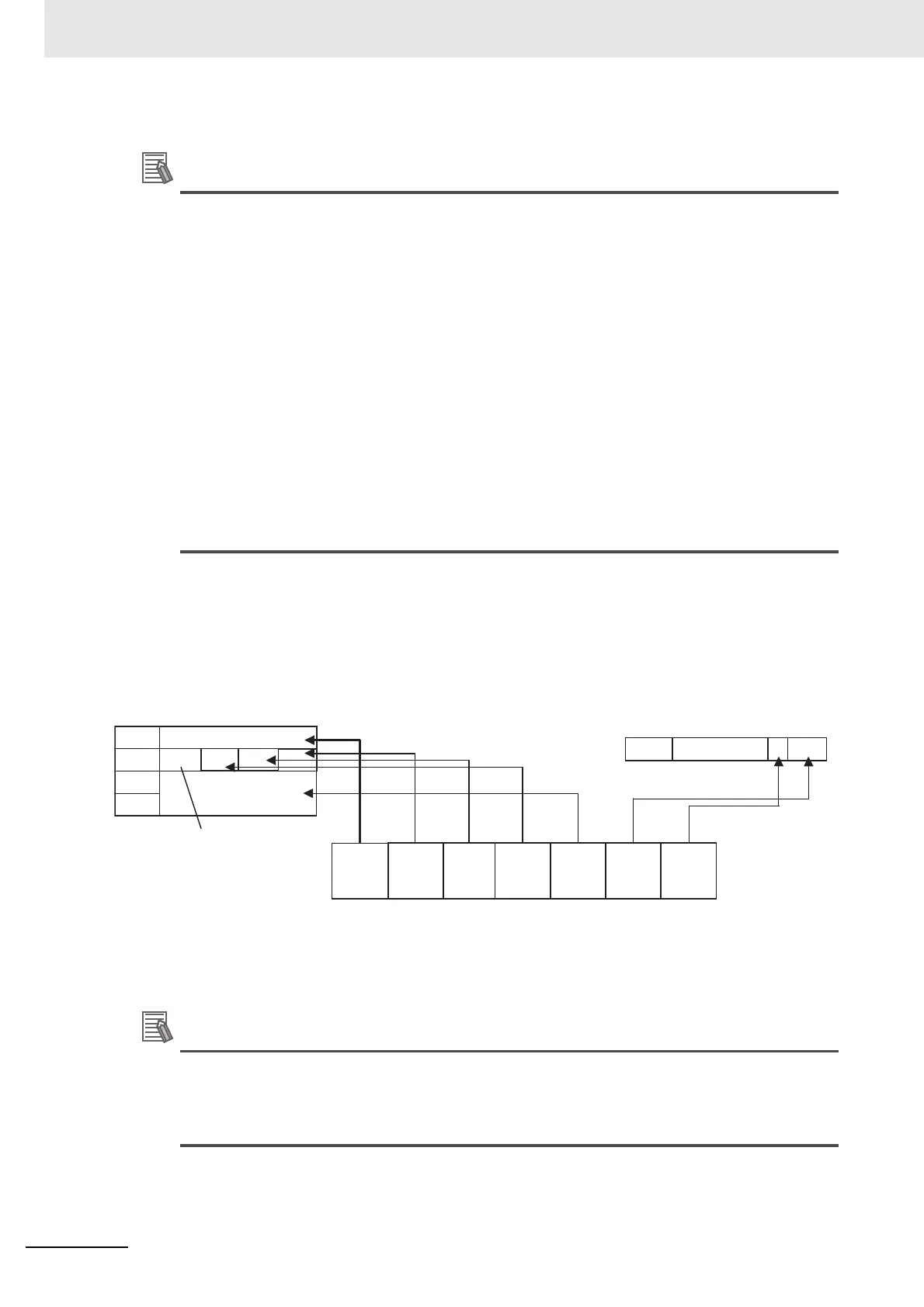
I/O Mapping Example
I/O data is mapped to the EtherNet/IP Coupler Unit’s I/O data blocks in the same order the NX Units
are connected to the EtherNet/IP Coupler Unit, regardless of the NX Units’ models.
The example below shows the I/O data mapping to the Input / Output blocks.
The following example shows the mapping of NX Output Units.
• Refer to the appropriate NX-series User’s Manual for more information on NX Unit data allo-
cation sizes.
• Refer to 9-2 Setting Slave Terminal Parameters on page 9-7 for more information about sta-
tus data configuration.
Word
15 8
0
Word
15 8
0
Some areas may be unused
when data is mapped.
Unused
First word
First word Unused
Output area
Input area
#6 #5
#6
#5
#4#3
#2
#1
EtherNet/IP Coupler Unit Status
EtherNet/IP
Coupler
Unit
NX-ID3317 NX-ID3317 NX-ID3317 NX-AD2203 NX-OD3121 NX-OC2633
#1
#4
#3 #2
+3
+1
+2
 Loading...


