9 - 71
9 Setting Up Slave Terminals
NX-series EtherNet/IP Coupler Unit User’s Manual (W536)
9-6 Assigning Network Vari-
ables
9
9-6-1 Basic I/O Mapping
9-6 Assigning Network Variables
Network variables are assigned in the PLC according to the I/O mapping created in the Support Soft-
ware. Use the following information to assign Network Variables in the PLC.
The numbers used to identify NX Units in a Slave Terminal are called Unit Numbers. These numbers
are allocated automatically from left to right starting with 1 when the power is turned ON. It is not neces-
sary for the user to set these numbers. The EtherNet/IP Coupler Unit will have a unit number of 0.
The type and order in which NX Units are mounted will determine the I/O allocation and will also affect
the Network Variable address assignments in the PLC. Refer to 9-5-5 Creating Tags and Tag Sets on
page 9-42 for more information about importing/exporting Network variables. The figure below shows
this mapping.
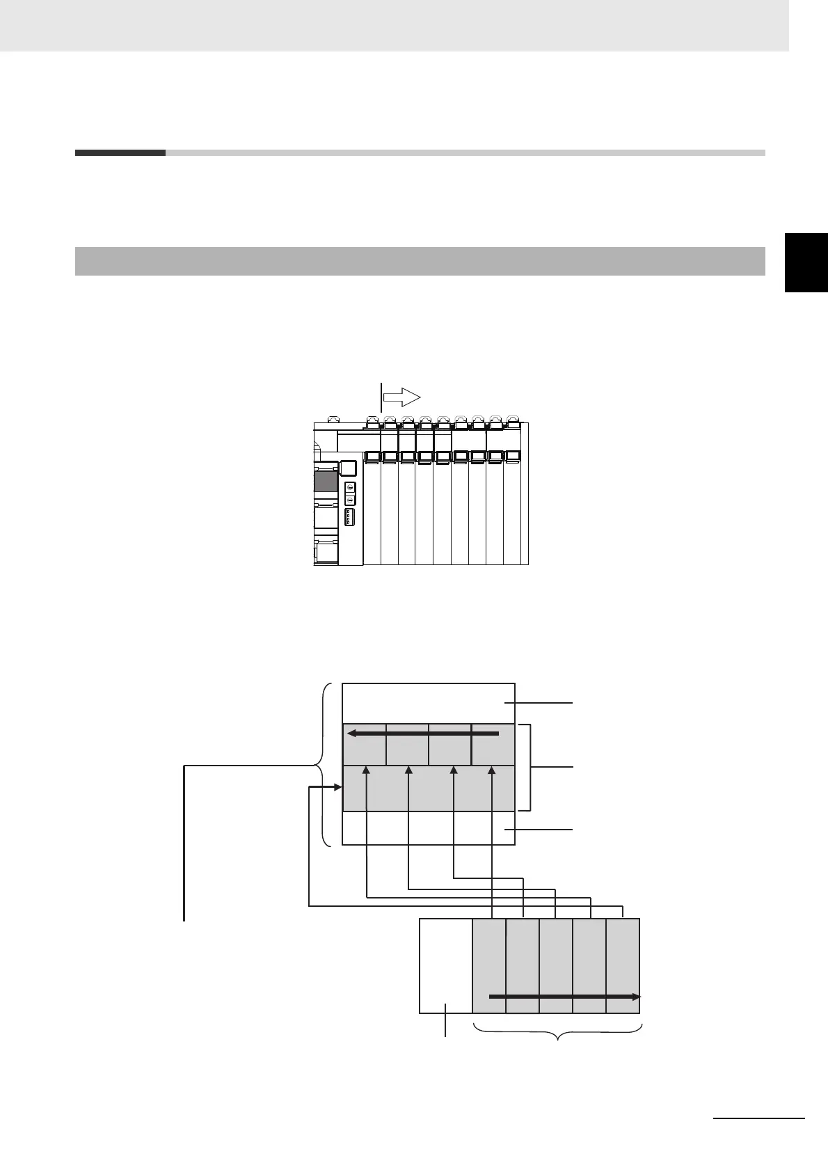
9-6-1 Basic I/O Mapping
... ...
I/O
#1
The NX Units’ unit numbers are allocated
automatically in order, from left to right.
I/O
#2
I/O
#3
I/O
#4 ...
I/O
#64
EtherNet/IP
Coupler Unit
E
Connected order
I/O memory
A
B
CD
E
EtherNet/IP
Coupler Unit
A
BC
D
NX I/O data is mapped in the order in which
the NX Units are connected, from low to high.
NX Units with bit allocation are mapped from
the rightmost to leftmost bit, in 2-bit units.
NX Units with word allocations are mapped
from the low to high word address
0
8
16
Order of allocation
Each NX Unit’s I/O data
EtherNet/IP Unit
EtherNet/IP Coupler Unit Status
 Loading...


