4 - 9
4 Part Names and Functions
NX-series EtherNet/IP Coupler Unit User’s Manual (W536)
4-3 Hardware Switch Settings
4
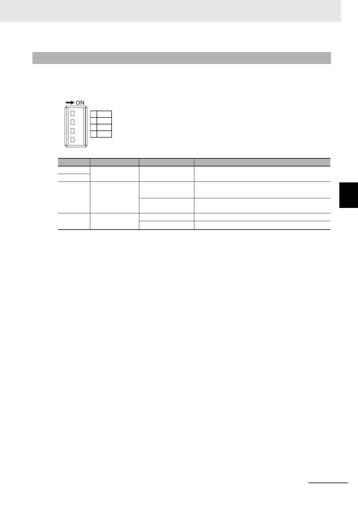
4-3-2 DIP Switch
Use DIP switch pin 3 to set the network interface type.
Use DIP switch pin 4 to set the base of the IP address for the EtherNet/IP network.
The other pins are reserved by the system.
4-3-2 DIP Switch
Pin Name Setting Description
Pin 1 Reserved by the
system
Keep turned OFF. ---
Pin 2
Pin 3 Network interface
setting
ON Enable TCP/UDP message service (disable tag data
links).
*1*2
*1. The following CIP services are unavailable when the TCP/UDP message service is enabled:
Tag data link (Class 1 connection)
Explicit message (Class 3 connection)
While the TCP/UDP message service is enabled, the EtherNet/IP Coupler Unit will return a Device State Con-
flict (0x10) CIP general error for a Forward_Open request.
*2. Network Configurator uses the UCMM type of explicit messages.
OFF (factory setting) Enable tag data links (disable TCP/UDP message ser-
vice).
Pin 4 IP address base
setting
*3
*3. Refer to 9-4 Setting IP Address on page 9-31 for information on setting the node address by combining the
rotary switches that are described above and pin 4 of the DIP switch.
ON 192.168.1. (with set by rotary switches)
OFF (factory setting) 192.168.250. (with set by rotary switches)
 Loading...


